 Facebook
 Google
 GitHub
 Linkedin
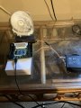
Hi. This is my first time posting to this website, so if I havent chosen the correct category/area to post this thread, then please excuse me. I ordered a rather inexpensive battery capacity tester from temu.com (around $6) and so far i have been using it to test the capacity of 18650 cells and other 3.7v lithium batteries. The module is designed for 18650 cells, but I have also been testing lithium polymer batteries on the module using alligator clips and wires to connect them up. The module has two large resistors labeled 10W8ΩJ that are used for the discharge cycle. I found an aluminium heat sink from a random board i had lying around that fits very well on top of the resistors. I used some thermal paste to place the heat sink on said resistors and have also placed a small fan that I pulled out of an old microwave in front of the resistors while the module is in the discharge cycle. I have been using an infrared thermometer to monitor the temperature of the resistors during disharge, and the temp is usually around 25-27 degrees Celsius. See the attached photo where I am testing a lithium polymer battery that I pulled out of a cell phone. I set up the fan and heat sink thinking that the module would run more efficently if I keep the resistors as as cool as possible. Is my thinking correct here, or should I allow the resistors to get hot in order for discharge to be more efficient?
Attachments
-
 2.2 MB Views: 16


