IR pair circuit troubleshooting

Thread Starter

bobparihar

Joined Jul 31, 2014
93
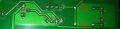
i am following a circuit of ir pair which i have seen in many tutorials
the circuit is given in the picture..i did followed same as the circuit but i dont know why its not working..
will any one please look at my circuit and just let me know where iam wrong..
the led connected is supposed to be off when some obstacle is in front of ir pair...
but its keep in the on state
 

Attachments

JohnInTX

Joined Jun 26, 2012
4,787
The output of the LM358 for the amp on pins 2-3 is connected to pin 7 on your board, not pin 1 as it should be.
It looks like only the wiper of the the pot is hooked up. EDIT: Looking again, I see where it is hooked up. Disregard.
R3 is missing.
R2 should be 220 on the schematic.
Make sure the photodiode D1 is sensitive enough and oriented correctly.
Consider using a comparator like an LM393N instead of an opamp for this kind of thing.
Good luck.
 
Last edited:

Thread Starter

bobparihar

Joined Jul 31, 2014
93
The output of the LM358 for the amp on pins 2-3 is connected to pin 7 on your board, not pin 1 as it should be.
It looks like only the wiper of the the pot is hooked up. EDIT: Looking again, I see where it is hooked up. Disregard.
R3 is missing.
R2 should be 220 on the schematic.
Make sure the photodiode D1 is sensitive enough and oriented correctly.
Consider using a comparator like an LM393N instead of an opamp for this kind of thing.
Good luck.

i have seen the same circuit i am following in a development board of arduino uno... and actually i have copied my circuit from there..
and its working fine there

look these are the pics of the board part containing IR pair ckt... and the ir pair on the board works fine the out is connected to the 1 pin of lm358... i also tried it but it doesnt work.. in fact once a time when i was doing on breadboard when i connect the out to 7th pin.. the circuit works... but after 5 minutes it does'nt
 

Attachments

Last edited:

JohnInTX

Joined Jun 26, 2012
4,787
.. in fact once a time when i was doing on breadboard when i connect the out to 7th pin.. the circuit works...
I don't think so. The two amplifiers are independent - pin 7 is not affected by the other amp. The inputs may have been floating around making that output switch.

If wired correctly with good parts, the circuit should work. To troubleshoot it:
Make sure the LM358 is good, power is good and correct and that the LEDs are in correctly.
Review the wiring on the breadboard - pins 3 and 4 have crossing wires that may hide a solder bridge or flake for example.
Measure the voltage across the IrLED - it should be Vf (about 1.5V) indicating that its ON. Some cellphone cameras will sense IR and you can see if its on.
Measure the voltage on pin 2 with and without IR reflection - it should vary, dropping as more light is sensed.
Measure the voltage on pin 3 and make sure it goes from 5V to 0V as the pot is turned then set it a little below the no-light voltage on pin 2.
Put something IR reflective in the light path and the voltage on pin 2 should drop to something below that set by the pot on pin 3. The output of the amplifier should flip from high to low.

That's really about it. Good luck.
 
Top