IR 2110- simulation

Thread Starter

rreddy426

Joined Jan 24, 2019
19
Hello All,

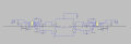
I am new to power electronics. I am trying to simulate full H bridge circuit. For driving FETs I am using IR 2110 as driver and I am using LT spice tool for simulation. downloaded IR 2110 model from infineon tec website. attached is the simulation set up. I can see output from "LO" pin, but not from "HO" pin. Out put from "HO" is zero.I don't understand what is the reason behind it. Any help is appreciated.

In the output blue line is from "HO" pin and green is "LO" pin

Thanks,
 

Attachments

eetech00

Joined Jun 8, 2013
4,705
Thanks ee Tech for your timely help. would you tell us what that series resistance do and adding "start up " do.
All voltage sources have series resistance. The voltage actually falls to some voltage close to zero but not actually zero. So specifying 100 milliohms just made the signal more "realistic". Likewise, all pulse sources have rise and fall time, so added that as well.

The "startup" option ramps up the voltage sources from 0s to 25us kind of like a real power supply when first powered on.
This helps any capacitors charge correctly during the simulation. If you don't use this option, then you are expected to know what the initial voltage and currents should be at various points of the circuit and set them using .IC statements. Sometimes that needs to be done but it depends goals of the simulation. Its easier to use "startup" first and then perform more settings if needed. You'll learn what's needed as you gain more experience with the tool.

eT
 

Thread Starter

rreddy426

Joined Jan 24, 2019
19
Hi,

I have one more question on Full bridge rectifier. When I connect load , then voltage drops to 5v. without any load across terminals, I am seeing 120 V. Not sure why voltage drops when a 1ohm resistor is connected
 

Attachments

wayneh

Joined Sep 9, 2010
18,104
Hi,

I have one more question on Full bridge rectifier. When I connect load , then voltage drops to 5v. without any load across terminals, I am seeing 120 V. Not sure why voltage drops when a 1ohm resistor is connected
Can you post a better picture of your schematic? Also, what happens if the load is say, 1K-10KΩ ?
 

Alec_t

Joined Sep 17, 2013
15,118
In your sim the VS terminal is not being pulsed, so the boost capacitor does nothing useful and the VB terminal won't rise high enough to drive the high-side FETs.
 

Thread Starter

rreddy426

Joined Jan 24, 2019
19
Huh? 0Ω is a dead short and I doubt the simulation will show a voltage across a dead short.

I intentially created a short here to see potential difference across the terminals. with 10K ohms measured voltage across terminals is 5V and is with 0ohm resistor I am observing 5 V.
 
Top