Inverting resistance and range of Fuel level sender

Thread Starter

Mike L1969

Joined Dec 15, 2024
7
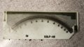
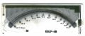
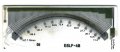
Been reading some old threads about adapter circuits for fuel level senders and thought I might as well give this a try. My '86 TBird came with the base option of an analog fuel gauge which uses a fuel level sender with specs of 60-86 ohms 'Empty' and 8-12 ohms 'Full'. I'm swapping in the optional full electronic digital cluster for this car, but the digital cluster requires a sender with specs of 11-16 ohms 'Empty' and 155-165 ohms 'Full'. Not only is this inverse to the base sender, but the range is a bit off. The sender for the electronic cluster is long out of production, and the old used one I found was worn out and not serviceable.

I'm seeking the expertise of the members here to perhaps guide me in an OpAmp circuit I could build and mount somewhere along the circuit to the cluster that would correct the resistance and allow the use of the base sender. I have some basic PCB design and fab experience 30 years ago.

Any and all help is greatly appreciated. There are likely many TBird owners who could find this info helpful!
 

MrChips

Joined Oct 2, 2009
34,628
There is conceivably an analog solution using an op amp to invert, amplify and offset to suit the requirements of the gauge.
Another solution is to use a small MCU and go digital. Measure the resistance of the sender, use a look-up table, and send PWM or whatever to the readout. This is easily transferable to any sender and any gauge.
 

crutschow

Joined Mar 14, 2008
38,322
Measure the resistance of the sender, use a look-up table, and send PWM or whatever to the readout.
But knowing the resistance doesn't necessarily tell you what voltage is needed to the gauge.

What's needed for easy conversion from the sensor resistance to the meter reading, is a measurement to determine what voltage range the gauge needs to go from empty to full.
Knowing the meter's resistance range doesn't really help that conversion.
 
Last edited:

MrChips

Joined Oct 2, 2009
34,628
I don’t think it matters. If we assume that both the sensor and the gauge are non-linear, what is needed is a calibration curve covering the entire range from empty to full for both sender and gauge.
 

Sensacell

Joined Jun 19, 2012
3,769
It's a fuel gauge, most of these are only vaguely accurate, the bar is low here.

Just calibrate for span and be done with it.
 

crutschow

Joined Mar 14, 2008
38,322
I don’t think it matters.
It matters whether you have the resistance values or the voltage values.
Just having the resistance values is not sufficient, since it's difficult to electronically simulate a varying resistance but easy to generate a voltage.
The digital gauge circuitry is unknown, so how would you determine the needed needed voltage from just the resistance values of the sender?
How many readings would suffice?
If you can, measure the voltage to the digital meter for 0, 1/4, 1/2, 3/4, and full settings of the "card" connected as both would be powered In the vehicle.
 

Thread Starter

Mike L1969

Joined Dec 15, 2024
7
Looking at the picture, is it feasible to recreate that card? Not sure what the resistor blocks along the top consist of, but the traces are somewhat straight forward. Also, I can measure resistance along each "wire" trace (where not broken) and also on each "pad" at the bottom.
 

Thread Starter

Mike L1969

Joined Dec 15, 2024
7
Here are the Ohms readings at each pad as shown. The RH of the card has a 9.4 Ohms pad where the wire was soldered to (broken) and all readings are off that pad. "Full" is LH end (approx. 155-165 Ohms) and "empty" is RH end (approx. 12.0-14.0 Ohms)
 

Attachments

crutschow

Joined Mar 14, 2008
38,322
Here are the Ohms readings at each pad as shown. The RH of the card has a 9.4 Ohms pad where the wire was soldered to (broken) and all readings are off that pad. "Full" is LH end (approx. 155-165 Ohms) and "empty" is RH end (approx. 12.0-14.0 Ohms)
That's good info, but the voltage that generates when connected to the digital gauge is what is needed to design the appropriate conversion circuit.
 
Last edited:

crutschow

Joined Mar 14, 2008
38,322
I'll have to get that, but it will take dropping the tank, I believe.
No.
I'm referring to the voltage that the digital sender generates when connected to the digital gauge.
You don't necessarily need the sender, you just need the equivalent resistance for the test.
You stated "the digital cluster requires a sender with specs of 11-16 ohms 'Empty' and 155-165 ohms 'Full'." so you just need resistors of about 13 ohms, 50 ohms, 90 ohms, and 160 ohms to give the approximate empty, 25%, 50%, 75% and full readings.
You could also use a 200 ohm pot to vary the resistance.
 

Thread Starter

Mike L1969

Joined Dec 15, 2024
7
No.
I'm referring to the voltage that the digital sender generates when connected to the digital gauge.
You don't necessarily need the sender, you just need the equivalent resistance for the test.
You stated "the digital cluster requires a sender with specs of 11-16 ohms 'Empty' and 155-165 ohms 'Full'." so you just need resistors of about 13 ohms, 50 ohms, 90 ohms, and 160 ohms to give the approximate empty, 25%, 50%, 75% and full readings.
You could also use a 200 ohm pot to vary the resistance.
I will need to drop the tank to get to the wires at the sender. I can then unplug the harness and hook up a volt meter along with a few decade box combos to approximate various sender conditions, to get the voltage.
 

BobTPH

Joined Jun 5, 2013
11,463
I will need to drop the tank to get to the wires at the sender. I can then unplug the harness and hook up a volt meter along with a few decade box combos to approximate various sender conditions, to get the voltage.
To expand in what @crutschow is saying (I think):

The sender is not producing a voltage! It is the meter that produces the voltage. You determine that by simply connecting a resistance to the meter inputs. Vary it from the low to high resistance (11 to 165 Ohms) and read the voltage across each resistor. Then you can control the meter by sending it those same voltages.

You do not need any access to the sender to do this.
 
Last edited:

Thread Starter

Mike L1969

Joined Dec 15, 2024
7
I understand what both of you are saying. But I do not want to disassemble the dash (again!) to access the cluster harness. I wouldnt be dropping the tank to measure the sender resistance (although I will have to do that eventually to measure the analog sender in the same way I measured the digital sender)... I'd be dropping the tank to unplug the sender and measure the complete circuit and voltage from the gauge at the sender connection point. This would include the entire circuit, which would likely be a more accurant voltage than directly off the fuel level cluster trace of the cluster circuit, which would be awkward and very tight confines... tedious.
 

GetDeviceInfo

Joined Jun 7, 2009
2,270
I have the "card" from the bad sender, and can take readings from across the range. I do know its not exactly linear as "half" is around 100 Ohms. (vs 169-11 /2 = 79 ohms)

How many readings would suffice?
Reverse the polarity on your 'card'. It looks to have the values your require. should be room for a jumper. Non linearity might be applied to tanks that are irregular in shape. If so, your mid ranges may be off, but high and low should be close.
 
Last edited:
Top