Facebook
 Google
 GitHub
 Linkedin

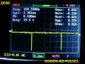
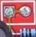
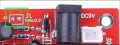
Is this (the green square i marked) the cal? output that you are refering? What is "cal"? calibration? It says J2 there 1kHz/3.3V and a square wave. Where should I add the wire? On A or B?On the scope circuit board there is a cal output test point in the little rectangle to the left of the power connector. Solder a short piece of stiff wire through the hole on the right. Leave it sticking up about 1/4" and trim it flush at the back. You can then use it as a quick input reference source because it is a 1Khz square wave with an amplitude from 0 to 3.3V
And 1inch = 2.54cm and 2.54/4 = 0.635cm or 6mm. Which is like a pin as short. Its very short.
And that can be a source of oscillation for something to be tested. I think I understand you.
Please confirm if is good or bad everything I said so far.
And thank you ! Very interesting ! I love it already.
Last edited: