Introduction to measuring with a Digital Oscilloscope (DSO138)

Status
Not open for further replies.

Audioguru again

Joined Oct 21, 2019
6,826
The absolute maximum allowed input is 50V peak. But 220VAC electricity is 311V peak or a little more and it will explode the circuitry of your oscilloscope. A 10:1 probe will divide the input voltage then the 311V will be 31.1V.
You asked about adding a 10k resistor in series with the scope's input but the resistor will pass the 311V and destroy the scope's circuitry.

I said to use the horizontal and vertical inputs with stereo signals since all oscilloscopes have a horizontal input except this one. The horizontal input is what moves the trace sideways (horizontally), the timebase.
 

Thread Starter

q12x

Joined Sep 25, 2015
2,227
Wire up a 555-timer oscillator circuit on your breadboard and use the DSO138 to analyze the circuit by looking at the square wave output on pin-3 and the control signal on pin-6.
I did it. I used this circuit :
SIMPLEST 555 OSCILLATOR.jpg
And I got a square wave on its output pin3.
I instinctively (or some back memory) zoomed in and out. It seems its maximum zoom resolution is 50us. It's very good. I also got a tricky square wave on one zoom level and noisy on other zoom level, but it turned out it was in a zoom level that was very fast to the display to render, probably, and when I zoomed in towards its maximum, I got a good result every time I stepped down or up, especially in the minimum range of its resolution. In the 100-10-1 ms. Test passed excelente.
But I also got some serious spikes in the square. I know many said on youtube about these spikes is because the tool itself has its limitations. I am aware of that.
Now... next thing to do?
 

Thread Starter

q12x

Joined Sep 25, 2015
2,227
I think... the best answer to someone like me, the osciloscope is to measure if something is broken or not, and to find why is broken. Correct? I remember some guys on youtube trying to figure out on a big motherboard where the shitty component got burned, between hundreds of smd's. That was mad to do and to watch, but very good experience for me to see it.
 

Thread Starter

q12x

Joined Sep 25, 2015
2,227
The absolute maximum allowed input is 50V peak. But 220VAC electricity is 311V peak or a little more and it will explode the circuitry of your oscilloscope. A 10:1 probe will divide the input voltage then the 311V will be 31.1V.
You asked about adding a 10k resistor in series with the scope's input but the resistor will pass the 311V and destroy the scope's circuitry.

I said to use the horizontal and vertical inputs with stereo signals since all oscilloscopes have a horizontal input except this one. The horizontal input is what moves the trace sideways (horizontally), the timebase.
Excellent explained, thank you !
Hmmm, you give me an idea. Is there a circuit that can "buffer" between 220 and the osciloscope? Like a step down voltage, very safe for the osciloscope. I think...probably a transformer will be fine for that... hmmm. I dont know. Its an idea.
 

Thread Starter

q12x

Joined Sep 25, 2015
2,227
And don't believe the Tektronics and HP BS as these are generic probes of decent quality. Basically the same probes shipped with chinese mfg scopes. Cleqee has a decent reputation but they don't make them, only paste their label on them..
So...doesnt matter the brand they have, they all have the same plug and the difference is minimum or nothing at all.
I find on ebay this cheap thing, because I look first on the price.
I think is good enough, no?
https://www.ebay.com/itm/P6100-100M...902354?hash=item54922133d2:g:AwMAAOSwWxNYtM2a
 

dl324

Joined Mar 30, 2015
18,403
There is some benefit to using Tektronix probes with compatible Tek scopes. When you do that, the probe bandwidth is actually a system bandwidth. So using a 100MHz probe with a 100MHz scope, the system attenuation at 100MHz will be 3dB. For a generic probe, the probe and scope would likely each be 3dB down at 100MHz.

Another advantage of 10X Tek probes on a compatible scope is that the on-screen readout will be adjusted (shifted one decimal place) so the displayed voltage will be correct. On an incompatible scope, you'd need to multiply the displayed voltage by the probe attenuation factor.
 

Audioguru again

Joined Oct 21, 2019
6,826
Keep away from 220VAC, it can kill you.

Your 555 circuit produces voltage spikes because it is missing the important supply bypass capacitors at the IC supply pins shown and explained in the datasheet for the 555. Also the many too-long jumper wires on a breadboard have inductance and the capacitance between all the jumper wires and the many rows of contacts have capacitance. Inductance and capacitance together form a resonance at the frequency of the spikes.
 

Thread Starter

q12x

Joined Sep 25, 2015
2,227
Another advantage of 10X Tek probes on a compatible scope is that the on-screen readout will be adjusted (shifted one decimal place) so the displayed voltage will be correct. On an incompatible scope, you'd need to multiply the displayed voltage by the probe attenuation factor.
Very good explanations ! Thank you.
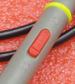
I buy that probe for $5.89. It also has this switch between 1x and 10X. That is very good and convenient to have.
1612225574657.png
So, I will use the 10x probe when I deal with high voltages, right? But not very high like 220 that I should keep the distance to not burn the oscilloscope.
Ok, now what should I test for ?
Or that's it?
 

Thread Starter

q12x

Joined Sep 25, 2015
2,227
Keep away from 220VAC, it can kill you.
I am dead inside for a long time. Nothing left to kill. Seriously.
And is not me but the tool that I want to protect. Me, I can heal, but the tool will be dead forever.
Your 555 circuit produces voltage spikes because it is missing the important supply bypass capacitors at the IC supply pins shown and explained in the datasheet for the 555. Also the many too-long jumper wires on a breadboard have inductance and the capacitance between all the jumper wires and the many rows of contacts have capacitance. Inductance and capacitance together form a resonance at the frequency of the spikes.
Very cool explained ! i love it.
Any more test ideas? (Fun) Circuits?
I will try your idea with the sound from the headphones. That is very smart thing to test.
 
Last edited:

Thread Starter

q12x

Joined Sep 25, 2015
2,227
Another very important problem:
How to protect my new osciloscope from high voltage spikes?
What do you recommend ?
If I measure an unknown circuit, and in it lurkes some high voltage? How to prevent it? How to prevent surging into my tool? With a protection circuit of some sort? Or a protection component? Between the osciloscope probe and the unknown potential high voltage circuit under test.
Thank you.
 
A couple of comments:

1. Find a case
2. If the DC supply is grounded, understand the implications.
3. The hardest thing used to be getting a trace, then getting a stable trace.
4. The input Z is usually 1M shunted by 22pf (common), 50 ohm or switchable.
5. using it in 1x mode generally means you have less bandwidth than specified.
6. Adding a 10x probe changes the input Z from 1M to 10 M. 10M is typical DVM input Z
6a. Just thrown in. Vintage voltage readings that are especially used in calibration might be specified as 50kohms/V input Z. It matters, especially in calibrating tube testers.
7. Compensation: there is a capacitor on the probe somewhere, In 10x mode and with a square wave applied, the capacitor is adjusted so the square wave is square. The cable has some capacitance and the scope has some capacitance. the idea witht he adjustable capacitor is to make the division by 10 purely resistive.
8. There are x100 and x500 probes too. You do have to match the capacitance (be close anyway).
9. Coupling AC: Just shows the time varying part of the signal
10. Coupling DC: Shows the non-time varying part + the time varying part.
11. Know the maximum input.
 

KeithWalker

Joined Jul 10, 2017
3,608
On the scope circuit board there is a cal output test point in the little rectangle to the left of the power connector. Solder a short piece of stiff wire through the hole on the right. Leave it sticking up about 1/4" and trim it flush at the back. You can then use it as a quick input reference source because it is a 1Khz square wave with an amplitude from 0 to 3.3V
 

MrChips

Joined Oct 2, 2009
34,948
Another very important problem:
How to protect my new osciloscope from high voltage spikes?
What do you recommend ?
If I measure an unknown circuit, and in it lurkes some high voltage? How to prevent it?
Thank you.
Stay away from high voltages for now. Start off by knowing the expected operating voltage of your devices.
Digital is 5V or 3.3V these days.
Analog tends to be around ±15V or lower. Stick with these circuits for now until you know how to handle higher voltages.

An oscilloscope is not just for finding faulty components. There are two many uses of the oscilloscope to list here.
That is why I say it is your #1 essential piece of test equipment if you want to get serious in this field.
 

MrChips

Joined Oct 2, 2009
34,948
If you are testing an LM555 or NE555 timer IC expect to see a lot of spikes in your circuit.
Try a CMOS version such as LMC555 or TLC555 or ICM7555 if you can find one.
 

SamR

Joined Mar 19, 2019
5,510
Keysight has some excellent video tutorials @ Keysight University

Scopes are for seeing time-variable signals. 10X has several uses other than high voltage such as noise reduction although I rarely rarely use 10X.
 

Thread Starter

q12x

Joined Sep 25, 2015
2,227
Stay away from high voltages for now. Start off by knowing the expected operating voltage of your devices.
Digital is 5V or 3.3V these days.
Analog tends to be around ±15V or lower. Stick with these circuits for now until you know how to handle higher voltages.

An oscilloscope is not just for finding faulty components. There are two many uses of the oscilloscope to list here.
That is why I say it is your #1 essential piece of test equipment if you want to get serious in this field.
Excellent advices. Thank you. Though I know many of these things, but when I get confirmation from you guys, it starts to print better in my brain as defaults. Thats why you are so helpful to me.
I will try my best to stay away from high voltages then.

If you are testing an LM555 or NE555 timer IC expect to see a lot of spikes in your circuit.
Try a CMOS version such as LMC555 or TLC555 or ICM7555 if you can find one.

...LM555 or NE555 timer IC expect to see a lot of spikes....
Yes it is a NE555. I don't have any other types. So it is normal then. And also as mister @Audioguru again said, the spikes are also from the breadboard metal strands as capacitance I didn't mention but he guessed right since he knows how I work from so many times I posted here.
What should I test next, mister @MrChips ?
An opamp? I think an osciloscope is to check if my circuit is behaving correct, and I think I can correct the circuit, by watching it with the osciloscope. Correct? In a word, for designing a circuit.
 

Thread Starter

q12x

Joined Sep 25, 2015
2,227
Keysight has some excellent video tutorials @ Keysight University

Scopes are for seeing time-variable signals. 10X has several uses other than high voltage such as noise reduction although I rarely rarely use 10X.
Excelent ! I think I buy this new probe because as you all mentioned here, or only you? it will be better for shielding interference than the alligator ones. Even If I dont use the 10x as you mention, then is good to have it as an option when necessity calls. I think 10x is more like a "zoom in", more detailed and fine tune things to measure. I am guessing here big time. :) I hope im right. But until it arrives, eheee, another millennia will pass.
 

SamR

Joined Mar 19, 2019
5,510
The keyword for 10X is attenuation, both the signal and noise. Don't remember if that scope has signal filtering as the full-sized scopes do. This is only needed when the signal is greater than the scope max. As Mr. Chips said, stick to low voltage stuff for now.
 
Status
Not open for further replies.
Top