Interface PCB giving erratic output signals after 6 months.

Thread Starter

shetsachin

Joined Jul 5, 2017
23
I have designed interface PCB. It is giving errotical output signals after using 6 months.This PCB interfacing between DIO PCI card to PLC.
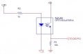
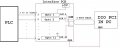
DIO card has +5v logic. & PLC has +24V. From PLC 11 outputs taken, max frequency is 2Khz duty cycle 50%. In interface PCB these signals are opto isolated (from +24v to +5v) then this output given to DIO Card connected using 2 feet cable.What is the cause for failing after 6 months.I have checked components optocoupler & regulator IC working fine.Not understanding is this a PCB design issue or component issue.Track size 0.3mm from opto output to DIO connector.

Please help anyone regard this.Attached Block schematic.
 

Attachments

Picbuster

Joined Dec 2, 2013
1,058
Failing after period of time but no fail in circuits will normal point to cables and connectors in special the grounding.
It's hard to give you a solution without proper information.

Picbuster
 

DickCappels

Joined Aug 21, 2008
10,661
It was a cute typing error but ack on topic, please.

The CTR (Current Transfer Ratio) of light emitting optelectric couplers lower as the LED ages, the main factors in aging being drive current, temperature, and time.

Questions to ask:
Are the coupler's inputs being driven too hard?
Is the output circuit tolerant of degraded CTR?

Back in the early 1980's when optocouplers were first used for feedback in isolated off-line switchers few if any paid attention to degrading CTR until there was a plague of dead products because of this overlooked problem.
 

Thread Starter

shetsachin

Joined Jul 5, 2017
23
It was a cute typing error but ack on topic, please.

The CTR (Current Transfer Ratio) of light emitting optelectric couplers lower as the LED ages, the main factors in aging being drive current, temperature, and time.

Questions to ask:
Are the coupler's inputs being driven too hard?
Is the output circuit tolerant of degraded CTR?

Back in the early 1980's when optocouplers were first used for feedback in isolated off-line switchers few if any paid attention to degrading CTR until there was a plague of dead products because of this overlooked problem.

Thanks for reply DickCappels,
TLP291 optocoupler is used.
Only half of IF current utilized.
 

Attachments

MrSoftware

Joined Oct 29, 2013
2,273
The first step is to figure out why you're getting bad readings. Put a scope on your inputs to be sure that the inputs are still what you're expecting. If they are, then work your way up the circuit until you find the component where the problems begin. Once you know why the readings are bad, then you can start to figure out what the cause is. If you think your components are OK, maybe check your connections, make sure they are clean and free of corrosion. Maybe reflow any components that look marginal and see if that helps.
 

Lyonspride

Joined Jan 6, 2014
137
I've had some issues recently with various devices (mostly sensors) not behaving properly, but then I realise that all the problems started after fitting a powerline adaptor to get ethernet in my workshop. They do seem to put lot of noise onto the mains supply and in my case it was going straight through my bench powersupply to the tune of nearly 60mV.

Could it be that you've done something similar? perhaps even your neighbour?
 

Thread Starter

shetsachin

Joined Jul 5, 2017
23
The first step is to figure out why you're getting bad readings. Put a scope on your inputs to be sure that the inputs are still what you're expecting. If they are, then work your way up the circuit until you find the component where the problems begin. Once you know why the readings are bad, then you can start to figure out what the cause is. If you think your components are OK, maybe check your connections, make sure they are clean and free of corrosion. Maybe reflow any components that look marginal and see if that helps.

Thanks for reply,
I have checked the Inputs & outputs of signal.Seems good.connectors are ok.Problems causes while long run.
I think may be need more capacitors for Power supply.because of many switching outputs & inputs.
 
Top