 Facebook
 Google
 GitHub
 Linkedin
Hello Everyone,
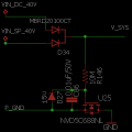
I have made the attached inrush current limiting circuit for a device powered by a PV panel / SMPS (40V/5A). The dual anode diode is for ORing and reverse polarity protection. Followed by the N-Channel low side Inrush limiter. On the secondary side (V_sys) there is a 8 cell LiFePo4 charger with some large capacitances (>3000uF) for other reasons.
Now the problem is the inrush works only the first time, the next time I power up the inrush does not work and I find that the FET is damaged. I have tried this multiple times and have the same results.
What am I doing wrong here? Pease help.
Regards
Richa
Attachments
-
 4 KB Views: 64


