Input capacitor gets very hot

Thread Starter

myil

Joined May 2, 2020
145
Hi Everyone,

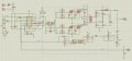
Input capacitor of my push-pull converter gets very hot. I checked it when the output power was about 100W. It was almost about to burn. Why is that? Is that the high input current that makes it very hot? Is there a way to avoid it?

Regards
 

Attachments

Dodgydave

Joined Jun 22, 2012
11,285
Are we talking about C3?

Your circuit is Far too complicated for Voltage feedback, a simple resistor ladder and preset will do on pin 1, as your using the same Ground you don't need an optocoupler.
 

Thread Starter

myil

Joined May 2, 2020
145
Are we talking about C3?

Your circuit is Far too complicated for Voltage feedback, a simple resistor ladder and preset will do on pin 1, as your using the same Ground you don't need an optocoupler.
No,I am talking about C6. 4700uf Electrolytic capacitor.
 

Irving

Joined Jan 30, 2016
3,845
i thought he meant C6... Need to know what the 12v supply is from, the ripple (demand) current from the inverter could be significant and if thats not a low esr type it will heat up. What spec is it?

C3 is an output capacitor IMHO...
 

Thread Starter

myil

Joined May 2, 2020
145
Then I would say you're getting back emf feedback into the capacitor, try an inductor on the input feed to the centre tap, and a Shockley diode for back emf suppression.
Is there another way to suppress back emf? I made a pcb that I don't want to ruin much. What if I replace a shottky diode paralel to R25,C5 and R26,C4?
 
Last edited:

DickCappels

Joined Aug 21, 2008
10,152
Electrolytic capacitors are rated for various temperatures. If you don't already have one, get a means of reading the temperature of the case and compare it with the capacitor's rating (often printed on the plastic jacket). You should probably also get the datasheet and see what the ripple current rating is for the frequency at which you are operating the capacitor. You should not exceed either rating.

If indeed the capacitor is being used outside its rating the generally accepted solution is to swap it out for the right capacitor or add capacitors to spread the stress among more capacitors.
 

crutschow

Joined Mar 14, 2008
34,285
If C6 is a standard electrolytic capacitor than it is likely the high ripple current from the inverter is causing the heating.
You need a low ESR electrolytic capacitor designed for switching power supplies.
 

Ian0

Joined Aug 7, 2020
9,680
1. Are your power cables too thin? As everyone says, you need a low ESR capacitor, but the lower your supply impedance, the lower the capacitor ripple current.
2. The back EMF doesn't go into the capacitor, it ends up on the drains of the MOSFETs and it makes them avalanche if the voltage gets too high. Back EMF will give you dead MOSFETs not a dead capacitor, so not likely to be the problem. Your transformer primary and the coupling between the two halves, is what causes back EMF. Your snubbers should take care of it, but if not, rewind the transformer, and perhaps add some zeners across the snubbers.
3. People should take care to say Schottky diode (after Walter Schottky) when they mean Schottky diode and Shockley diode (after William Shockley) when they mean Shockley diode. The former is a metal semiconductor junction which works like an ordinary diode but with lower forward voltage drop, and the latter is like a diac.
4. Is this circuit for an inverter? So there will be a further stage which generates two 50Hz sinewaves for live and neutral?
If so then isolated feedback will be mandatory because the NEUTRAL output must be earthed to pass safety legislation.
One thing is true, though, even for isolated feedback it's too complicated!
 

Thread Starter

myil

Joined May 2, 2020
145
Thanks for all great comments here. Yes, I am using low esr capacitor. I measured it that says ESR is less than 0.00 ohm. But some cheap Chinese capacitors, so I don't know how reliable they are .
 
Last edited:

Thread Starter

myil

Joined May 2, 2020
145
1. Are your power cables too thin? As everyone says, you need a low ESR capacitor, but the lower your supply impedance, the lower the capacitor ripple current.
2. The back EMF doesn't go into the capacitor, it ends up on the drains of the MOSFETs and it makes them avalanche if the voltage gets too high. Back EMF will give you dead MOSFETs not a dead capacitor, so not likely to be the problem. Your transformer primary and the coupling between the two halves, is what causes back EMF. Your snubbers should take care of it, but if not, rewind the transformer, and perhaps add some zeners across the snubbers.
3. People should take care to say Schottky diode (after Walter Schottky) when they mean Schottky diode and Shockley diode (after William Shockley) when they mean Shockley diode. The former is a metal semiconductor junction which works like an ordinary diode but with lower forward voltage drop, and the latter is like a diac.
4. Is this circuit for an inverter? So there will be a further stage which generates two 50Hz sinewaves for live and neutral?
If so then isolated feedback will be mandatory because the NEUTRAL output must be earthed to pass safety legislation.
One thing is true, though, even for isolated feedback it's too complicated!
No, my power cables are not too thin. Yes, my circuit is for an inverter. how can I lower my supply impedance? I am using an automotive battery.
 

bob2

Joined Jun 15, 2019
224
I measured it that says ESR is less than 0.00 ohm. But some cheap Chinese capacitors, so I don't know how reliable they are .
How could a capacitor with an ESR of less than 0.00 ohm be the source of the problem?
If possible, measure D.
 

Thread Starter

myil

Joined May 2, 2020
145
How could a capacitor with an ESR of less than 0.00 ohm be the source of the problem?
If possible, measure D.
I can normally measure 0.01 ohm but if it's less than that, it shows as 0.00 :D I know it sounds weird but I don't have a fancy pancy expensive equipment to measure.
 

BobaMosfet

Joined Jul 1, 2009
2,110
@myil - get a datasheet for that capacitor- it sounds like you are exceeding a parameter. Also, electrolytics are polarized- I could be wrong, but your schematic doesn't seem to show polarity for C6.
 
Last edited:
Top