 Facebook
 Google
 GitHub
 Linkedin
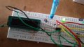
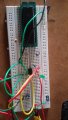
IR TX & RX
Hello Frnds I want to do a project based on IR Sensors
I bought IR sensor pair but i cant found which one is transmitter and which one is receiver
Please give me a solution
Hello Frnds I want to do a project based on IR Sensors
I bought IR sensor pair but i cant found which one is transmitter and which one is receiver
Please give me a solution
Last edited by a moderator:


")


