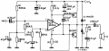
I have an ongoing project to build an induction loop to link to the telecoil receivers in my hearing aids. As background I was curious to know how a loop amp can efficiently drive up to 10A peak round a loop with resistacce of only 0.2 - 2 ohms. So I tried tracing the circuit of our disused PDA500 loop amp. From a visual inspectio, it cotains a LM1875 power amp and 2 complementary BJTs BD911 and BD912, presumably to boost the output current drive capability. Tracing the cirtcuit, and after double-checking, this is what I got:

Clearly, this is going to instantly blow both BJTs then blow the (slo-blo) fuses! Very strange also that the LM1875 supply appears to be fed from the BJT bases. Continuity checks show that the collectors are indeed tied together and tied to the LM1875 output, that the emitters are connected to the positive and negative supplies and that the bases are connected to the LM1875 supply pins. The amplifier worked immediately before decommissioning, though with a bit of noise and distortion on the output, possibly due to an aging LM1875.
Something must be wrong. But in my experience, if double-checking doesn't reveal your mistake, triple checking rarely does either. But 3rd party checking often spots the mistake instantly. Who'll be my 3rd party?