Facebook
 Google
 GitHub
 Linkedin
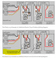
I just wired two new 15 amp circuits to my breaker box with a duplex breaker. I used 14-3 wire and put the red wire to one breaker and the black to the other.
When testing the circuit with only one of the two breakers (the black wired one) on I saw 120vac between between white and black but 67vac between white and red. It reversed when I switched which circuit breaker was on.
I think this is simply and induced current in the off wire and I should not worry am I correct?