 Facebook
 Google
 GitHub
 Linkedin
Hello everyone! This is my first post on the forums, and I have questions about a specifics on a project I am working on.
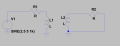
Description of the project: I am using a DAC run by an Arduino to create a 5 Vpp with 2.5 DC offset Sine wave of 1kHz (frequency has been varied for testing). The Sine wave is put through a resistor in series with copper coils that I created. My thought is that the sine wave will go through the coils to create a magnetic field. Separate from the transmitting(TX) circuit, I have another coil trying to receive the magnetic field.
Goal: Have the receiving coil act like a position sensor so that if it is close enough to TX coil, it will output a voltage.
I realize this is everything a hall effect sensor is and an IC can do this job, but my requirements require that the sensor/receiver be flat(flatter than the IC packages). My next step was to move on to design a planar coil, but I ran into the problem of not receiving any sine waveforms on the receiving coil. The only signal seen is 60 Hz noise.
Somethings I've tried in different orders and not necessarily together:
Questions:
Some specs I found while investigating that might help:
Coil diameter = 14.05 mm
Number of turns = 30-40
Multimeter measured TX current : 173.22uA
The maximum distance the two coils will be apart is about 90mm.
In the waveform capture, yellow is the RX coil's output probed between the resistor and coil. Red is what is going into the TX coil.
Let me know if more information is needed. Any suggestions or advice is appreciated!
Thanks!
.png")

Description of the project: I am using a DAC run by an Arduino to create a 5 Vpp with 2.5 DC offset Sine wave of 1kHz (frequency has been varied for testing). The Sine wave is put through a resistor in series with copper coils that I created. My thought is that the sine wave will go through the coils to create a magnetic field. Separate from the transmitting(TX) circuit, I have another coil trying to receive the magnetic field.
Goal: Have the receiving coil act like a position sensor so that if it is close enough to TX coil, it will output a voltage.
I realize this is everything a hall effect sensor is and an IC can do this job, but my requirements require that the sensor/receiver be flat(flatter than the IC packages). My next step was to move on to design a planar coil, but I ran into the problem of not receiving any sine waveforms on the receiving coil. The only signal seen is 60 Hz noise.
Somethings I've tried in different orders and not necessarily together:
- Put the sine signal through an op amp to get it to 8 volts peak to peak.
- filter out the 60 Hz noise
- moved a magnet back and forth in front of one coil(works so theory holds up)
Questions:
- Am I wrong to assume that the receiving coil should see a sine wave on the output? Or is it possible that the magnetic field strength is so weak in the coil that the RX coil is actually receiving the magnetic field but it doesn't show on the scope.
- Ideally, if the RX coil moves closer to the TX coil, wouldn't the amplitude measured on the RX coil increase?
- What kind of circuitry would I need to measure if the peak to peak voltage is large enough (the RX coil is close enough to the TX coil)
- Would using something like a hall plate be more effective than a coil?
Some specs I found while investigating that might help:
Coil diameter = 14.05 mm
Number of turns = 30-40
Multimeter measured TX current : 173.22uA
The maximum distance the two coils will be apart is about 90mm.
In the waveform capture, yellow is the RX coil's output probed between the resistor and coil. Red is what is going into the TX coil.
Let me know if more information is needed. Any suggestions or advice is appreciated!
Thanks!
Attachments
-
 142.3 KB Views: 0


