Incremental encoders help

Thread Starter

daljeet795

Joined Jul 2, 2018
295
Hello everyone

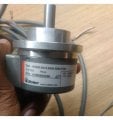
I have encoder 8.5000.0010.5000.0050.F030 and I am looking datasheet for wiring. I found the datasheet on google but I am not sure it's exact same for my model.

I have attached document

upload_2019-2-24_22-46-18.png

please somebody take a look at the document's and help me to understand wiring connection
 

Attachments

MisterBill2

Joined Jan 23, 2018
18,176
We need a MUCH better image of the MODEL number, not the serial number. My analysis is an RS422 output, which is useless in many applications. So since the model number allegedly provides all of the details we must have a readable image of it. The serial number is only possibly useful in communicating with the manufacturer.
 

MaxHeadRoom

Joined Jul 18, 2013
28,619
My analysis is an RS422 output, which is useless in many applications. .
With incremental encoders as I believe it is in this case, the RS422 does not refer to the composition of the signal but the nature of the output, IOW a typical A, A\ & B, B\ complementary output IC differential line driver.
It is also shown alongside the other two forms, which is achieved with a either Push-pull and open collector.
RS422 or (RS485) is a very common line driver output in the CNC/servo world and is the type I always use if possible due to its inherent noise free nature.
Max.
 
Last edited:

MaxHeadRoom

Joined Jul 18, 2013
28,619
@daljeet795 It is a RS422 quadrature 5v differential output with 5000 p/rev, this would give you 20,000 pulses if x1, x2 or x4 the natural count, if needed.
You need to show or detail the pin count to clarify the connections or point to the one in the PDF.
Max.
 
Last edited:

MaxHeadRoom

Joined Jul 18, 2013
28,619
You do not necessarily require the sense, this is just to detect encoder loss.
Also if only needing single-ended just the two A & B pulses can be used.
They appear to have used strange notation for what I presume is the marker pulse, generally Z, Z\ (pins 3 & 4) is used not 0, 0\.
Also for differential output, 5v dc is typically used.
Max.
 
Last edited:

MisterBill2

Joined Jan 23, 2018
18,176
Checking the encoder with a multimeter will only allow you to verify that the outputs are changing states as they should be, it will not provide any other information. The very difficult part of the testing will be connecting to the pins on the connector, if you do not have access to a matching mating connector.
If the encoder has been installed in some piece of equipment and you are checking to make sure that it is still functioning then I suggest using the same supply voltage as it has in that installation.
For checking, you must be able to turn the encoder by hand, very slowly. Connect the multimeter, set to a DC voltage range that includes the supply voltage, to the common supply negative side. The supply positive must be connected to the encoder positive supply connection as shown in the drawing in post #10, using the connector layout as shown in post #8. Then connect the meter to pin 5 and slowly rotate the encoder. The voltage should rise and fall as it rotates. Next connect to pin 6, again it should rise and fall. Next, repeat the same with pins # 8 and then pin#1. The voltage should rise and fall in a similar manner. The last check will be the reference pulse connections, connect to pin #3 and the voltage should stay high for most of the rotation, except for one point. Finally, connect to pin #4, and the voltage should stay low except for one position. This test verifies that all of the outputs are functioning and that the encoder disk is not broken or otherwise damaged. It also verifies that the connections in the cable are still connected. . If you need to verify that the outputs and complements are correctly opposite that is a separate test that can be done.
 

MisterBill2

Joined Jan 23, 2018
18,176
Can you explain why the encoder needs to be tested? Is there a problem with the installation? or are you verifying the condition of a spare encoder?
 

MaxHeadRoom

Joined Jul 18, 2013
28,619
@daljeet795 The resolution of the encoder you have is fairly difficult to test with a meter due to the frequency of change that will occur with just a Very small movement of the shaft.
A change in .072 of a degree!
A 'scope, if you have one would be a more conclusive test, do you suspect this one?
Max.
 

MisterBill2

Joined Jan 23, 2018
18,176
Max, it seems that the TS has no access to a scope, which is why the request for a meter.. Certainly it will be a challenge to view the states but it is indeed possible with a steady hand and patience. Been there and done it, and even with a much higher resolution linear encoder it is possible. Tedious , certainly, but possible. The TS just needs to verify that transitions are happening a bit.
 

Thread Starter

daljeet795

Joined Jul 2, 2018
295
@daljeet795
A 'scope, if you have one would be a more conclusive test, do you suspect this one?
Max.
Max, it seems that the TS has no access to a scope, which is why the request for a meter...
hello Max & MisterBill2

I don't have a scope that's why wanted to check using a multimeter

I am thinking to check encoder with a microcontroller and led. I have never worked on the encoder
 

MisterBill2

Joined Jan 23, 2018
18,176
hello Max & MisterBill2

I don't have a scope that's why wanted to check using a multimeter

I am thinking to check encoder with a microcontroller and led. I have never worked on the encoder
I was aware that when you asked for a meter checking test that you did not have access to a scope. I never had a scope out on the production floor either. Scopes are for work in nicer environments. and with the money that a scope would cost we could get a lot of other supplies and tools. The substitute for a scope is insight and understanding.
 

MaxHeadRoom

Joined Jul 18, 2013
28,619
Actually a fairly cheap alternative and works well in both field and shop is the dual beam Digital storage 'scope that simply plugs into the USB port of a laptop.
My Syscomp does the trick for me. https://www.syscompdesign.com/
Are you checking as to whether it is operational or for interest?.
Max.
 
Last edited:

MisterBill2

Joined Jan 23, 2018
18,176
I am a hobbyist and I wanted to use encoder in a project so just checking it

so I don't have the option to check it manually so I think I have to test it c program
The multimeter test that I described will verify the functionality of the encoder, but not the accuracy. And it does work.
 
Top