Increasing power (12v) starts smocking wires

Thread Starter

crazybuoy

Joined Sep 19, 2010
77
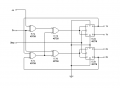
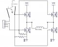
I created stepper bipolar driver with 4070 & 4027 as shown in attached image and used H-bridge made of 8 N-mosfets (IRFZ44n). It works or turns the motor (3 ohm winding resistance) fine when supplying 12V to CMOS circuit and 5V to N-mosfet h-bridge. The mosfets don't turn hot while working.

But when
I supply 12V to N-mosfet h-bridge. It starts smocking wires like a short-circuit, it also does not turn motor and all mosfets turns hot very fast. Why it does in this way? H-bridge should also work at 12V like 5V. What is missing here?

Note: I'm using ATX power supply.
 

Attachments

crutschow

Joined Mar 14, 2008
38,532
What is missing here?
The fact that the N-MOSFETs require a gate voltage 10V higher than the source voltage (Vgs) to fully turn on, as specified in the data sheet.
upload_2017-1-31_20-12-58.png
You need a driver for the top MOSFETs that can supply 22V to their gates if you want to run the bridge at 12V.
This can be provided by a gate driver IC with a built-in charge pump to generate the required voltage such as the MC33883.

Alternately you can use P-MOSFETs for the top transistors which can be fully turned on by connecting their gates to ground (sources connected to Vcc).
 

Thread Starter

crazybuoy

Joined Sep 19, 2010
77
Alternately you can use P-MOSFETs for the top transistors which can be fully turned on by connecting their gates to ground (sources connected to Vcc).
Thanks for your expert reply. I could not understand, can you please show it in a small drawing.
 

LesJones

Joined Jan 8, 2017
4,511
The mosfet needs the gate to be 10 volts positive of the source to turn the mosfet fully on. You will achive this with the lower two mosfets as their source terminals are connected to zero volts. The source terminal of the top two mosfets is NOT connected to zero volts. Yoy are trying to switch them fully on so you are trying to get the source voltage to near +12 volts. So if the source is at +12 volts and the gate needs to be 10 volts positive of the source then the gate needs to be 22 volts positive of ground. (12 + 10 = 22)

Les.
 

Thread Starter

crazybuoy

Joined Sep 19, 2010
77
the gate needs to be 22 volts positive of ground. (12 + 10 = 22)
That is a nice explanation and calculation. but how can I put following line into practice? I am looking the practical drawing for it..

Alternately you can use P-MOSFETs for the top transistors which can be fully turned on by connecting their gates to ground (sources connected to Vcc).
 

LesJones

Joined Jan 8, 2017
4,511
Read crutschow's post #02 again. He has given you three options. For the first option with the extra 22 volts supply and sill using an N-mosfet you could use an NPN transistor to amplify the output from the 4027B ICs to give 0 to +22 voltt pulses. (Note the transistor will invert the signal) The second option using the MC33883 (For which has provided the link to the data sheet.) You would need to study the data sheet to make sure your drive waveform would allow the charge pump to work properly. The third option changing to P-mosfets for the upper mosfets would only require a drive signal of 0 to +12 volts. (NOTE the P-mosfets would be switched on when the drive signal was at zero volts.)

You need to do some of the work yourself and not expect to be provided with the complete design.

Les.
 

Thread Starter

crazybuoy

Joined Sep 19, 2010
77
Option one: Using NPN transistor to amplify signal as shown in image (H-bridge only N). The 4027 has four outputs (1a, 1b, 2a, 2b). Do I need to attach one NPN transistor to all four output pin?
To run N-mosfet H-bridge at 12V, gate volts need to increase 21V and to drive it at 30V, does Mosfet gate volt need to increase 40V?

Option two: If I use n-p mosfet h-bridge, do I need not any signal amplifier for h-bridge? Can I drive n-p mosfet h-bridge at any volt (5-40) easily?
 

Attachments

crutschow

Joined Mar 14, 2008
38,532
If I use n-p mosfet h-bridge, do I need not any signal amplifier for h-bridge? Can I drive n-p mosfet h-bridge at any volt (5-40) easily?
You will need the following:
Below is the LTspice simulation of a complementary MOSFET bridge.
The circuit on the left is a non-overlap drive circuit so that both MOSFETs on the same side are not on at the same time.
Otherwise you can have large shoot-through currents which can significantly increase the MOSFET dissipation.
This is a concern with all bridge types, whether all the same type MOSFETs or complementary.
Note that the MOSFET gate signals 1 and 2 to the bridge don't overlap, insuring that one pair of MOSFETs is off before the other come on.

The MOSFETs can be any type that have sufficiently low on-resistance and voltage rating for your motor.

It's not shown but all the logic circuits are connected to 12V Vcc.

The logic gates can't go much above 15V, so to run the bridge above that voltage, you will need a separate supply for the logic (10V minimum to drive the N-MOSFETs unless they are logic-level types).
Also most MOSFETs can't tolerate a Vgs greater than 20V so you will need a clamp or voltage divider on the P-MOSFET gates to insure Vgs stays below their maximum rating if you run the bridge at or above that voltage.

Edit: Updated Schematic to provide better MOSFET gate drive.

upload_2017-2-5_9-34-0.png

Note that the unused gate inputs on the CD4001 should be connected to ground.

(Incidentally, I think the word you want is smoking. :))
 

Attachments

Last edited:

Thread Starter

crazybuoy

Joined Sep 19, 2010
77
That is really a great design. :eek: I am very thankful for that and I'm sure now there will not be any SMOKING :).

I think, there only half part of 4027 (only two output 1a & 1b) will be used to drive N-P Mosfet h-bridge. Is it?
I mean two non-overlap drive circuits for two half h-bridges.
Please tell me if I am right.
 
Last edited:

crutschow

Joined Mar 14, 2008
38,532
I think, there only half part of 4027 (only two output 1a & 1b) will be used to drive N-P Mosfet h-bridge. Is it?
I mean two non-overlap drive circuits for two half h-bridges.
Please tell me if I am right.
Not quite. :)
You would use signals 1A for one bridge and 1b for the other bridge. (I assume this is a two-phase motor drive).
And you need one non-overlap drive circuit for each bridge.
 

Thread Starter

crazybuoy

Joined Sep 19, 2010
77
(I assume this is a two-phase motor drive
I want to drive a bipolar stepper motor (3 ohm winding resistance and 4kg weight).

At 12V input to bridge, you used 10k resistor at gates of P-Mosfets. What resistor to use if I increase voltage 12 to 24 or 40 (for example)?

And you need one non-overlap drive circuit for each bridge.
It means, one half 4027 (1a & 1b) will be used to drive two non-overlap drive circuits and two bridges to drive one bipolar stepper motor. So one 4027 can drive two bipolar stepper motors.

Am I right?
 

crutschow

Joined Mar 14, 2008
38,532
At 12V input to bridge, you used 10k resistor at gates of P-Mosfets. What resistor to use if I increase voltage 12 to 24 or 40 (for example)?
You need two added resistors in series above 20V to limit the Vgs to no more than 20V.
Thus for you would leave the 10kΩ and add a 10kΩ ohm resistor in series from the N-MOSFET drains to the gates for 24V, and 15k for 40V.
It means, one half 4027 (1a & 1b) will be used to drive two non-overlap drive circuits and two bridges to drive one bipolar stepper motor. So one 4027 can drive two bipolar stepper motors.
Sorry that was a typo.
You need signal 1a to go to one bridge non-overlap circuit and signal 2a to go to the other bridge non-overlap circuit.
 

Thread Starter

crazybuoy

Joined Sep 19, 2010
77
Now, everything is clear to me. I will try it asap.

[̲̅T̲̅][̲̅h̲̅][̲̅a̲̅][̲̅n̲̅][̲̅k̲̅][̲̅ ̲̅][̲̅Y̲̅][̲̅o̲̅][̲̅u̲̅]

You need signal 1a to go to one bridge non-overlap circuit and signal 2a to go to the other bridge non-overlap circuit.
In the same way, can I use 1b & 2b instead of 1a & 2a.
 

crutschow

Joined Mar 14, 2008
38,532
I forgot to add in post #13 that the CMOS logic gates can't operate much above 15V so for bridge voltages above that you will need a regulator, such as an LM317, to generate 15V for the gates, if you don't already have a separate voltage for that.
 

ian field

Joined Oct 27, 2012
6,536
The fact that the N-MOSFETs require a gate voltage 10V higher than the source voltage (Vgs) to fully turn on, as specified in the data sheet.
View attachment 119724
You need a driver for the top MOSFETs that can supply 22V to their gates if you want to run the bridge at 12V.
This can be provided by a gate driver IC with a built-in charge pump to generate the required voltage such as the MC33883.

Alternately you can use P-MOSFETs for the top transistors which can be fully turned on by connecting their gates to ground (sources connected to Vcc).
Inadequate gate drive can cause excessive MOSFET dissipation - so can overlap.
 
Top