Increase current

Thread Starter

j3r

Joined Jan 9, 2011
15
Hi all, i need to drive a motor which takes in -20mA to 20mA. I got a module from NI, NI 9269

http://sine.ni.com/nips/cds/view/p/lang/en/nid/207638

Basically, this module only supports max of +/- 10mA, and i can't replace it with others as no other modules from NI suits my requirement of +/- 20mA. Therefore my solution would be have a simple circuit to "step up" the current to drive the motors. The circuit would be attached to the NI module at one end, other end would be connected to the motor. I've googled and search this forum, MOSFET would be an ideal choice. But i'm not quite good in electroics, how can i go about it. Can someone reckon me provide me some MOSFET which i look into?

MANY THANKS!!
 

#12

Joined Nov 30, 2010
18,224
Quote: The total output of all channels is +/- 20 ma. Page 12, operating instructions and Specifications. This means you can parallel 2 channels and get the current you need.

Check it out and see if I read it correctly.
 

SgtWookie

Joined Jul 17, 2007
22,230
You could use (an) opamp(s) wired as voltage followers/buffers to increase the current.
To wire an opamp channel as a voltage follower, wire the output to the inverting (-) input, and provide the input signal to the non-inverting (+) input.

You'll need an external power supply, of course. +12v/-12v would probably work with most opamps that are designed for dual supply operation.

L2722 dual power opamps will output up to 1A, and are quite inexpensive.
 

Thread Starter

j3r

Joined Jan 9, 2011
15
Quote: The total output of all channels is +/- 20 ma. Page 12, operating instructions and Specifications. This means you can parallel 2 channels and get the current you need.

Check it out and see if I read it correctly.
No we can't as the MAX output total current is limited to +/- 10mA.
 

Thread Starter

j3r

Joined Jan 9, 2011
15
You could use (an) opamp(s) wired as voltage followers/buffers to increase the current.
To wire an opamp channel as a voltage follower, wire the output to the inverting (-) input, and provide the input signal to the non-inverting (+) input.

You'll need an external power supply, of course. +12v/-12v would probably work with most opamps that are designed for dual supply operation.

L2722 dual power opamps will output up to 1A, and are quite inexpensive.
Thanks. I'm looking into this.
 

Thread Starter

j3r

Joined Jan 9, 2011
15
You could use (an) opamp(s) wired as voltage followers/buffers to increase the current.
To wire an opamp channel as a voltage follower, wire the output to the inverting (-) input, and provide the input signal to the non-inverting (+) input.

You'll need an external power supply, of course. +12v/-12v would probably work with most opamps that are designed for dual supply operation.

L2722 dual power opamps will output up to 1A, and are quite inexpensive.
I saw the datasheet, do you mean cascade the 2 op amps?
 

#12

Joined Nov 30, 2010
18,224
Page 13 confirms your statement. The max total output is 20 ma, but page 13 says you can't parallel for current, you can only do series connections for higher voltage.

Back to the drawing board!
 

thatoneguy

Joined Feb 19, 2009
6,359
What is the motor?

Is it rated for ±20mA at a certain voltage?

Typically, motors do not need to be current limited, only voltage regulated, which is why I ask.
 

#12

Joined Nov 30, 2010
18,224
This is the basic form you will need to use. I forgot to draw the connection from AO- to ground.

Now to select a center tapped transformer, full wave bridge rectifier, filter capacitors, and an op-amp that will deliver at least +/- 10 volts and 20ma (as instructed by the AO terminals).

There is room to tighten up the ripple, but motors are not very picky about that and op-amps are rather good at refusing to let the ripple through.

It's 2:30 am at my house. I must go to sleep now. C ya 2morrow.
 

Attachments

Last edited:

Thread Starter

j3r

Joined Jan 9, 2011
15
What is the motor?

Is it rated for ±20mA at a certain voltage?

Typically, motors do not need to be current limited, only voltage regulated, which is why I ask.
I don't have much info about the motor (sadly not even the dataheet :( 
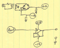
), basically its a thruster used in ROVs. I tested various voltages to achieve +/- 10mA as of now, the voltmeter reads +/- 1.8V.

I understand what you mean, since the load ( ie. motor) is fixed, therefore varying the voltage will induce varying current which drives the motor at different speed / direction.

With the current module i had from NI, i'm only able to go up to 10mA.

The only info i had is the +/- 20mA. Sorry about the little info i have at hand.
 
Top