In need of long imprecise timer for 230v ac electromagnet.

WBahn

Joined Mar 31, 2012
33,084
It was just an aluminum electrolytic. But since the device was mounted on an interior wall, it was always within a pretty narrow temperature range. So as long as the leakage current at that temperature in that specific capacitor was fairly repeatable then the timing was fairly repeatable. I don't know how well it would have handled aging effects over an extended period of time.

That's been so long ago that I don't remember the specifics. It was definitely a case of "fairly consistent" translating to "consistent enough" for the application. I think the times were usually within a minute of the target time, which was more than good enough for their needs and it sounds like within perhaps even five minutes of the target time might be good enough for this one.
 
Last edited:

Alec_t

Joined Sep 17, 2013
15,150
My (slight) concern would be that if the leakage current became equal to the feeble charging current then the timer would stop working, leading to premature demise of the hydroponics crop.
 

WBahn

Joined Mar 31, 2012
33,084
I would agree that that is the biggest concern. As long as the actual time constant is within something like 25% (shooting from the hip here) then I don't think the risk is too great. It would be a simple matter (I might try to do it when I get a chance) to quantify that tolerance, at least roughly, in terms of the ratio of the terminal charging current to the leakage current.

Note that while I do think that this is probably the simplest solution and that it is viable, it is pretty clearly not the best approach. Using a simple counter IC is a significantly better choice. Given the loose performance requirements, such a solution can be implemented pretty easily with only a few additional components.
 

Thread Starter

taith

Joined Apr 1, 2017
28
Almost soldered all on board, look wonderfully sketchy haha, last obstacle I went on was HFD41 relay.
There are no indications where coil is, but from outside package looks I went with outer pins to be electromagnet... Well I was surprised that after soldering all multimeter told me NOPE.
Looked at schematics and was like: WHY YOU DO IT LIKE THIS
 
Last edited:

Thread Starter

taith

Joined Apr 1, 2017
28
As I understand biggest concern is OFF line high resistance and low charging current, if I'll see delay getting too high I'll change resistor to 5k or so.
 
Last edited:

AnalogKid

Joined Aug 1, 2013
12,241
If you are building the schematic in post #15, a comment. If the intent of diode D1 is to protect circuit components from the relay coil inductive kick at turn-off, the diode is not in the correct location.

ak
 

Thread Starter

taith

Joined Apr 1, 2017
28
Circuit seem to work fine, while powered starts at ON stage that is slightly longer than rest of ON stages.
 

Alec_t

Joined Sep 17, 2013
15,150
Good to hear it's working but, as AK says (post #26), the diode is in the wrong place. It should go between pin 3 of the 555 and ground, pointing up. Sorry about that.
starts at ON stage that is slightly longer than rest of ON stages.
That's to be expected, as the cap has to charge from zero initially.
 

recklessrog

Joined May 23, 2013
985
Using a 555 for long delays can prove to be unreliable and does require high value low leakage capacitors, (although in this case not important) A better way would be to use the 555 as an oscillator running at a higher frequency, then use decade counters to divide the output to the frequency required. Alternatively maybe use two 555's as cross coupled monostables, 555 stability in monostable mode is considerably greater than astable or multivibrator mode.
 

Thread Starter

taith

Joined Apr 1, 2017
28
Good to hear it's working but, as AK says (post #26), the diode is in the wrong place. It should go between pin 3 of the 555 and ground, pointing up. Sorry about that.

That's to be expected, as the cap has to charge from zero initially.
Meaning I should connect (-) with OUT and diode should point towards OUT yes? (it still temporairly works with buzzer)
 

AnalogKid

Joined Aug 1, 2013
12,241
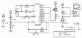
Finally got back to this. Here is a non-555 solution. Q8 and Q14 are 64x apart in timing. In round numbers one minute of off time gets you 1 second of on time. The circuit is adjustable from 5 to 10 minutes. I threw in an LED so you can see that it is operating correctly during the long off periods.

R1-C1 are a power-on reset. R2+R3 and C2 are the main timing components. The equation in on the 4060 datasheet. Assuming the circuit is adjusted for an 8-minute cycle:

Q14 is low for 8 minutes, disabling the reset input through D1. Q8 is cycling during this time and is ignored. The LED is flashing at approx. 1 Hz.

After 8 minutes, Q14 goes high, turning on the relay. The 4060 is a ripple counter, so this can happen *only* when all other outputs are low. This enables the reset input, but it is held low by Q8 through R5.

After 7.5 seconds, Q8 goes high. R5 is much smaller than R1, pulling the reset input high after about 15 ms.

The 4060 resets, all outputs go low, and the cycle repeats.

ak
Long-Timer-1-c.gif
 

Attachments

Last edited:

Thread Starter

taith

Joined Apr 1, 2017
28
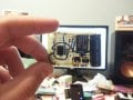
Here is finished circuit, have not had these soldered boards in shop, so went with what was there.
Also I am not a champion of circuit planning hah.
But it does work well.
Thank you everybody, hope it will get useful for anyone needing timed switch.
 

Attachments

Top