Facebook
 Google
 GitHub
 Linkedin
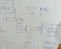
I need to make small electromagnet valve taken from washer to open for short period of time, and remain closed for longer period.
Electromagnet works at 230V AC, 40mA. Works on 230V DC as well.
Available power sources: 230v AC or 12v DC 1.2A.
It needs to power electromagnet for about 1-10s and then charge/wait for another 5-10min. Doesn't have to power electromagnet right away, it can charge mentioned 5-10min before turning on.
Does not have to be 1ms precise I look for some simple, cheap and reliable solution.
More wordy description:
The electronics steering it are working with use of 12v DC power supply (electronics take 100mA supply is 1.2A)
When probe detects PH to be too low or too high proper switch is closed.
Even more wordy description of system:
I have small potato hydroponic system and it require to adjust PH of nutrients at least 2 times a day, that means I can not leave it going by itself.
I have found cheap and simple automatic PH adjusting system for aquariums, however it only opens and closes circuit until PH reach set point.
Thing about hydroponics is slow self mixing process and slow PH probe response (the the more worn out probe the slower response). So it might end up dumping LOTS of PH regulator to system, burning roots. Dilluting PH- and PH+ are not best option as with 1:10000 dillution I could make it work but pure PH dilluting water added to system alone would cause problems (too much water dilluting nutrients, plants starve, water overflow).