 Facebook
 Google
 GitHub
 Linkedin
Hello, I want to solve the following problem. I need to optimally implement the following function using 4-to-1 multiplexers, using the smallest number necessary. The weight of the variables is (ABCD) = (8421). Identify each integrated circuit and all necessary connections, with the name and number of each pin.
NOTE: Only multiplexers and inverters should be used.
f = Maxterms(3, 7, 8, 10, 11)
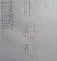
The first thing I did was to set up the truth table and compare the variable D with the output f ((D,f) column), obtaining the following:
A B C D F (D,f)
0 0 0 0 1 1
0 0 0 1 1 1
----------------
0 0 1 0 1 /D
0 0 1 1 0 /D
----------------
0 1 0 0 1 1
0 1 0 1 1 1
----------------
0 1 1 0 1 /D
0 1 1 1 0 /D
----------------
1 0 0 0 0 D
1 0 0 1 1 D
----------------
1 0 1 0 0 0
1 0 1 1 0 0
----------------
1 1 0 0 1 1
1 1 0 1 1 1
----------------
1 1 1 0 1 1
1 1 1 1 1 1
Then I get a simplified table
A B C F
0 0 0 1
0 0 1 /D
0 1 0 1
0 1 1 /D
1 0 0 D
1 0 1 0
1 1 0 1
1 1 1 1
According to the simplified table, I chose to use A for the mux enable inputs (which are active low), for the first I use A and for the second /A and B and C as selection inputs.
My question is that if I can only use NOT gates in addition to the MUX, how do I obtain a single output from each output of the multiplexers?
Which could simply be done using an OR gate whose inputs would be the output of each mux.
Thanks in advance for the help.
NOTE: Only multiplexers and inverters should be used.
f = Maxterms(3, 7, 8, 10, 11)
The first thing I did was to set up the truth table and compare the variable D with the output f ((D,f) column), obtaining the following:
A B C D F (D,f)
0 0 0 0 1 1
0 0 0 1 1 1
----------------
0 0 1 0 1 /D
0 0 1 1 0 /D
----------------
0 1 0 0 1 1
0 1 0 1 1 1
----------------
0 1 1 0 1 /D
0 1 1 1 0 /D
----------------
1 0 0 0 0 D
1 0 0 1 1 D
----------------
1 0 1 0 0 0
1 0 1 1 0 0
----------------
1 1 0 0 1 1
1 1 0 1 1 1
----------------
1 1 1 0 1 1
1 1 1 1 1 1
Then I get a simplified table
A B C F
0 0 0 1
0 0 1 /D
0 1 0 1
0 1 1 /D
1 0 0 D
1 0 1 0
1 1 0 1
1 1 1 1
According to the simplified table, I chose to use A for the mux enable inputs (which are active low), for the first I use A and for the second /A and B and C as selection inputs.
My question is that if I can only use NOT gates in addition to the MUX, how do I obtain a single output from each output of the multiplexers?
Which could simply be done using an OR gate whose inputs would be the output of each mux.
Thanks in advance for the help.
Attachments
-
 192.6 KB Views: 4


