Facebook
 Google
 GitHub
 Linkedin
Hey, can anyone help me with this?
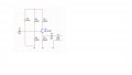
I have to make a emitter follower circuit.
I have to have a 600 ohm output impedance
10k input impedance
12V DC
20Hz
With BC547B transistor
I have to decide how much the resistors have to be.
I only know how to find impedances with the help of the resistors, not the other way around.
If someone just can help me with math formulas, I would be happy