I'm stuck on part A of a decoder.

Thread Starter

jessy1221

Joined May 15, 2018
7
thank you for all your help and advice, i was able to figure it out
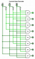
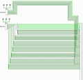
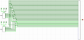
Hey. I have the same homework for my class and was wondering how you did part A and part B? I'm stuck on part A still. So far I've got 2 3:8 decoders, but don't really know where to go form there?


Mods Note:
Please don't hijack other member's thread.
This thread was split from -- Confused on how to make a counter does what I need it to do?
 

dl324

Joined Mar 30, 2015
16,943
Welcome to AAC!
I have the same homework for my class and was wondering how you did part A and part B? I'm stuck on part A still.
Post the work you've done so far and the complete text of the problem. What the OP posted was essentially unreadable.
 

Thread Starter

jessy1221

Joined May 15, 2018
7
I need to simulate a 0-7 gearbox. 1 input is to be the current gear (G), which is represented by 3 inputs, G1, G2, G3, and the other input is the gear to shift to (S) which is also represented by 3 inputs, S1, S2, S3. I need to change from the current gear to another gear. I can only use AND, OR and NOT gates, and I will be successful if S=G, or S=G-1, or S=G+1.

Once this is done, the car now has a gearbox that can withstand up to a number of unsuccessful gear changes (N) and it will break if that number is reached. The number N ranges from 1 to 7 and must be set via a combination of three separate inputs: N1, N2, and N3. An N value of 0 is not allowed and the gearbox state is undefined for this case. This means that you will have to set N to be non-zero (1..7) before starting the engine engaging the gearbox. I need to add additional circuitry to the original circuit to count how many successful and unsuccessful gear changes have been made. Each time an unsuccessful gear change is made, add 1 to the number of unsuccessful gear changes. Each time a successful gear change is made, add 1 to the number of successful gear changes. I can use only AND, OR, and NOT gates with maximum 2 inputs, as well as the more advanced counter, comparator, and DFLIP-FLOP circuits (only those three). Can also use a constant (3) to compare against successful gear changes. Additionally, I need to add a button that is pressed by me after the current Gear (G) and gear to change to (S) have been entered.

So far for the first part I've worked out that I need to make two 3:8 decoders and then a big selector which will combine the G inputs with the S inputs. But I'm struggling with how to put them together. I initially made a 64 bit selector, but there wasn't enough space to enter everything, so i made a larger one and now that one is too big. I'm thinking that I'm not connecting them properly.
 

Attachments

dl324

Joined Mar 30, 2015
16,943
So far for the first part I've worked out that I need to make two 3:8 decoders and then a big selector which will combine the G inputs with the S inputs.
I don't know how you're being taught, but the way you've labeled the gear inputs below seems backwards:
upload_2018-5-15_18-53-39.png
It's customary to use the smaller number (i.e. G1) to be the least significant bit and largest number (i.e. G3) to be the most significant. You've done the opposite.

Additionally, it makes more sense to start with 0 instead of 1 because that makes the digits represent the power of 2.

Is there a logical reason why you've inserted unnecessary bends in the wires coming from the G decoder and putting so much space between the two gear decoders and the circuit block on the right? What's in the tall circuit block on the right?
upload_2018-5-15_18-57-21.png
 

Thread Starter

jessy1221

Joined May 15, 2018
7
No, I was seeing if it all worked first and then if it did I was going to fix it up and make it neater later. The tall circuit block is the selector. Initially it was a 64 input selector what there wasn't enough room to add everything so I made it bigger and now its too big, hence why I think I'm not connecting it correctly.
 

Attachments

dl324

Joined Mar 30, 2015
16,943
The tall circuit block is the selector.
What is this selector supposed to do?

Somewhere in the text, it said you were restricted to 2 input gates, but you're using 3 input gates in the decoder. Can you use gates with more than 2 inputs?

What is your strategy for making sure that the new gear selection is within 1 of the current gear setting?
 

Thread Starter

jessy1221

Joined May 15, 2018
7
About the three inputs apparently we're allowed the have 2 3 inputs, it's very confusing. And the reason we're fixed on using 2 3:8 decoders is because that's one thing my teacher told me was correct. He also said we we need to connect the decoder outputs to AND gates, eg., G0 go's into and AND gate with S0, and another AND gate with S1. G1 goes into an AND gate with S0, an AND gate with S1, and an AND gate with S2 etc. I've done all that now but I'm still stuck on how to get the correct outputs.
 

dl324

Joined Mar 30, 2015
16,943
He also said we we need to connect the decoder outputs to AND gates, eg., G0 go's into and AND gate with S0, and another AND gate with S1. G1 goes into an AND gate with S0, an AND gate with S1, and an AND gate with S2 etc. I've done all that now but I'm still stuck on how to get the correct outputs.
Can you post exactly what your teacher said and your lecture materials/notes?

I think you missed an important bit of information. This appears to be a brute force approach and it's how you wire the "selector thing" that makes the circuit work or not work.

I implemented the solution using the approach I think your teacher wanted and it appears that everyone working on this problem has missed the same piece of information.
 
Last edited:

dl324

Joined Mar 30, 2015
16,943
Initially it was a 64 input selector what there wasn't enough room to add everything so I made it bigger and now its too big, hence why I think I'm not connecting it correctly.
I took a closer look at the 64 input selector and it will work if you use it correctly.
 

Thread Starter

jessy1221

Joined May 15, 2018
7
This is exactly what we have been given, nothing else:

You are required to implement a simple simulation of a gearbox in a car. The gearbox has two inputs. Input 1 (G) represents the current gear (0-7). Input 2 (S) represents the gear that the driver wants to change/shift to (0-7). The gear change is successful if S = G, or if S = G – 1, or if S = G + 1.Any other value for S outside of this range will result in an unsuccessful gear change.

Example 1: The current gear (G) is 2 and the gear we want to change to (S) is 3. In this case the requirement S = G + 1 is met and the gear change is successful.
Example 2: The current gear (G) is 2 and the gear we want to change to (S) is 4. In this case S is outside the allowed range and the gear change is unsuccessful.
Example 3: The current gear (G) is 0 and the gear we want to change to (S) is 0. In this case the requirement S = G is met and the gear change is successful.

The current Gear (G) will be represented by three inputs (3 bits). The three G inputs are named as G1, G2, and G3. The table attached shows the assignment of bits to each G value for G1, G2, and G3. The gear that we want to change/shift to (S) will be represented by three inputs (3 bits). The three S inputs are named as S1, S2, and S3. The table attached shows the assignment of bits to each S value for S1, S2, and S3.

And Also this:
The implementation for this must use only the three basic logic gates (AND, OR, NOT) with maximum 2 inputs. You are required to implement a circuit where the user (you) can input a value for the current Gear (G) using value (G1, G2, and G3) and a gear to change to (S) using value (S1, S2, and S3) and the circuit decodes the G1, G2, G3 and S1, S2, S3 values made up of only the permitted logic gates to determine if S = G, or if S = G – 1, or if S = G + 1. The output will be a single LED labelled Successful which is lit if S = G, or if S = G – 1, or if S = G + 1 and is not lit for any other values of S and G.

And the teacher just said in passing, nothign formal, that two 3:8 decoders with the outputs inputted into AND gates, where G0 AND S0, G0 AND S1, G1 AND S0, G1 AND S1, AND G1 AND S2, etc was correct.
 

Attachments

dl324

Joined Mar 30, 2015
16,943
And the teacher just said in passing, nothign formal, that two 3:8 decoders with the outputs inputted into AND gates, where G0 AND S0, G0 AND S1, G1 AND S0, G1 AND S1, AND G1 AND S2, etc was correct.
Work on implementing the circuit for G=1. Once you have that working, you can do the rest of the gear numbers.

I picked G=1 because the G=0 and G=7 are implemented differently than G=1-6.

Do it using whatever you need from the 64 bit selector.
 

Thread Starter

jessy1221

Joined May 15, 2018
7
I did it! I've got G1 to work, as well as G2, G3, G4, G5, and G6. Thank-you! I think I might have had them working before actually, and it was G0 and G7 which are stuffing me up. I'm trying to get those two to work now, but am having a bit of trouble. Do you have any hints?
 

Thread Starter

jessy1221

Joined May 15, 2018
7
So I've done it, I've successfully outputted the S=G, S=G+1, and S=G-1 using the simplified/subcircuit 64 input selector (I simplified it because that's required for the class). But I've found that I have a heap of extra inputs left on the selector. I've attached a picture. The lines are super long but I'll fix that up later.
 

Attachments

dl324

Joined Mar 30, 2015
16,943
But I've found that I have a heap of extra inputs left on the selector. I've attached a picture.
I used one of these for each of the gear numbers:
upload_2018-5-17_18-51-22.png
One AND gate wasn't used, but no simplification was possible. What are you simplifying?

The lines are super long but I'll fix that up later.
If you work more neatly from the beginning, you should be able to skip most of the "fixing"; which is essentially a waste of time. Being neater from the start makes it easier for you to get help too.

My preferred solution to this problem was to make a 3 bit comparator that returned true when the difference between the inputs was ≤ 1. It took a few dozen gates (your two input gate requirement would have probably doubled the number), but I think it's a more elegant solution.
 

dl324

Joined Mar 30, 2015
16,943
I've successfully outputted the S=G, S=G+1, and S=G-1 using the simplified/subcircuit 64 input selector (I simplified it because that's required for the class).
Take a closer look at your solution. You didn't implement G=0 and 7 correctly because you only handle 2 of the 3 conditions. And the logic for some of the other counts isn't using the correct selector inputs.

upload_2018-5-17_19-22-49.png

Did you test all possible combinations of G and S?
 

WBahn

Joined Mar 31, 2012
30,082
The advantage of the two 3-8 decoders is that the solution is then conceptually very easy. The simplest, brute force way is to use AND gates to test for all of the possible pass conditions (of which there are 22) and then OR them together to get the final output (which requires, if I counted right, 21 OR gates).

This can then be cleaned up quite a bit using a few different ways. The most elegant I can think of uses 7 OR gates between each adjacent pair of outputs of one decoder and then 6 OR gates between adjacent pairs of those. This produces 8 signals that can then be ANDed with the corresponding outputs of the other decoder and the outputs of the AND gates can be OR's together using 7 OR gates. So (in addition to the two decoders) a total of 20 OR gates and 8 AND gates. The 3:8 decoders can be done using 12 AND gates and 3 NOT gates (maybe less). So that makes the entire circuit take 32 AND gates (8 quad packages), 20 OR gates (5 quad packages) and 6 NOT gates (1 hex packages), or 58 gates.
 

dl324

Joined Mar 30, 2015
16,943
My solution required 12 4 input AND, 4 3 input AND, 4 2 input AND, 4 4 input OR, and 6 inverters; for a total of 12 chips. It used the binary gear inputs directly, so no 3:8 encoders which required 16 3 input AND and 6 inverters:
upload_2018-5-17_19-44-20.png
The counters and NAND were to automate testing.
 

WBahn

Joined Mar 31, 2012
30,082
So, assuming you can't share signals, a 4-input AND is three 2-input NANDs and a 3-input AND is 3 2-input ANDs. Same with the OR gates. So that would translate to a max of 48 2-input ANDs (twelve quad packages), 12 2-input ORs, (three quad packages), and 6 inverters (1 hex packages) for a total of 66 gates and 16 chips. Mine takes 14 chips. You might be able to get it down to that if you can share some of the intermediate signals that using two-input gates makes available.
 

dl324

Joined Mar 30, 2015
16,943
37 AND = 10 pkg
11 OR = 3 pkg
6 INV = 1 pkg
54 gates, 14 packages total

If I didn't make a mistake, that would make it a tie.
 
Top