Ignition system: bbq, propane, battery operated, not piezoelectric

cmartinez

Joined Jan 17, 2007
8,830
Many thanks

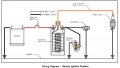
I did as you suggested and found this. It uses a car engine coil to build up a high voltage through induction. An oscillator circuit (not shown) produces a pulse into a MOSFET which starts the process.

All good. However, I don't understand why or if the spark plug is necessary. I don't know how spark plugs work. If the spark plug does something integral to the circuit then I can't use the circuit because it's an engineering problem I don't want to tackle to get the bulky plug into the burner.

Can the spark plug be replaced or dispensed with?
There's an important component missing in that diagram that you've posted. An inverse-parallel diode mounted across the coil's terminals (with its cathode pointing at +12V) is needed to protect the mosfet. Otherwise, after a few cycles, your transistor will generate magic smoke that is impossible to put back in. That is because the inductive load presented by the coils tries to kick current back into the mosfet when it is switched off, and that generates very high voltages, much higher than the transistor's rating. The diode takes care of those peaks by very briefly acting as a short circuit, dissipating them as heat.

An ordinary 1N4004 diode would work just fine for your application.
 

Thread Starter

Mellisa_K

Joined Apr 2, 2017
391
There's an important component missing in that diagram that you've posted. An inverse-parallel diode mounted across the coil's terminals (with its cathode pointing at +12V) is needed to protect the mosfet. Otherwise, after a few cycles, your transistor will generate magic smoke that is impossible to put back in. That is because the inductive load presented by the coils tries to kick current back into the mosfet when it is switched off, and that generates very high voltages, much higher than the transistor's rating. The diode takes care of those peaks by very briefly acting as a short circuit, dissipating them as heat.

An ordinary 1N4004 diode would work just fine for your application.
Got it! Thank you
 

Thread Starter

Mellisa_K

Joined Apr 2, 2017
391
A car ignition circuit is close to what you want, but there are some differences.

A car ignition has critical timing needs. The fuel-air mixture is highly compressed and easily ignited and the ignition has to occur within a very narrow time window of ten or twenty microseconds. So the circuit produces a single, high energy spark.

For a propane burner, the timing is immaterial but the fuel-air mixture is very low pressure and, relatively speaking, not as easily ignited. So a typical battery-operated circuit produces a number of relatively low energy sparks, only needing one of them ignite the mixture. Piezo circuits generally only produce a single spark, which is why you often have to activate them a number of times in order to get ignition.
Very useful remarks, thank you
 

Thread Starter

Mellisa_K

Joined Apr 2, 2017
391
Th
The tricky bit is the HV pulse transformer - they're available as salvage from gas stoves & central heating units.

Its essentially a CDI unit, one of the UK magazines did an almost copy of a commercial product.

You need a blocking oscillator converter to generate a tad over 250V. the project used a 1.5v cell, the pot core had 15T oscillator windings and a 250T HV secondary. 15R resistor in series with the base winding. can't remember the transistor type, but it was rated 80V in a TO5 can.

The capacitor discharge bit uses a Siemens high energy discharge device with 220V breakdown - they sometimes turn up on telephony gear and modems. You might get away with an SCR if you drive the gate via a diac fed by divider resistor from the HV reservoir cap, they break over somewhere around 32V ish.

The capacitor is 1uF - at the time, the only survivable type found was made by ITT, but others exist.
Thankyou I'll look into that by googling these key words. So much to learn!
 

-live wire-

Joined Dec 22, 2017
959
Let me clarify something. Those types of HV generators, along with everything else, must obey this law: power in > power out (greater than because there are always losses). Power is voltage times current (P = V*I). So step up the voltage, and the current goes down (or power up). But there is another important concept. Time. For example, a capacitor can be charged up as slowly as you want. But then you can get many kW out of it for a tiny fraction of a second. So it is more precisely average power in > average power out.

What does this mean for you? Well, almost all of those HV generators use a circuit involving HV capacitors. While they may supply many amps at 10s of kV, it is for a tiny fraction of a second (a few times per second). HV naturally poses certain risks, and such high momentary currents can still be harmful, but it is pretty unlikely that it will cause significant harm, or fatal electrocution. The average current, given by the power law, is tiny.

Others have said it supplies uAs, but that is just average. It is not the whole picture. Such HV still poses these risks:
-UV and harmful radiation from arcs
-nerve damage due to momentary currents, more so a concern if continuously zapped
-ozone gas generation
 

Thread Starter

Mellisa_K

Joined Apr 2, 2017
391
Let me clarify something. Those types of HV generators, along with everything else, must obey this law: power in > power out (greater than because there are always losses). Power is voltage times current (P = V*I). So step up the voltage, and the current goes down (or power up). But there is another important concept. Time. For example, a capacitor can be charged up as slowly as you want. But then you can get many kW out of it for a tiny fraction of a second. So it is more precisely average power in > average power out.

What does this mean for you? Well, almost all of those HV generators use a circuit involving HV capacitors. While they may supply many amps at 10s of kV, it is for a tiny fraction of a second (a few times per second). HV naturally poses certain risks, and such high momentary currents can still be harmful, but it is pretty unlikely that it will cause significant harm, or fatal electrocution. The average current, given by the power law, is tiny.

Others have said it supplies uAs, but that is just average. It is not the whole picture. Such HV still poses these risks:
-UV and harmful radiation from arcs
-nerve damage due to momentary currents, more so a concern if continuously zapped
-ozone gas generation
Good advice

Thankyou
 

jbeng

Joined Sep 10, 2006
84
If you're interested in using an automotive ignition coil to generate the spark to light your oven, do a google search for the old-school "kettering ignition" systems. They are very simple; a battery, a switch, a capacitor (called a condenser), an ignition coil & a spark gap. That's pretty much it. Here's one of the many images you will see. Substitute a normally open pushbutton switch for the breaker points. You will get a single (hot) spark from the coil output to ground when you press & release the switch.
.
Kettering.jpg
 

-live wire-

Joined Dec 22, 2017
959
Additionally, why do you need an arduino here? Is it going to be part of an automated "smart oven"? If you just need pushbutton operation, why not use a 555, Schmidt relaxation, or other oscillator like that? I see no need for an arduino, unless you are only using it for prototyping. There are even limitations and other issues, with only a 16MHz clock. There are far better ways of getting PWM. Even if as a beginner a circuit seems too complicated, you can usually just follow it exactly and get the desired result.
 

Thread Starter

Mellisa_K

Joined Apr 2, 2017
391
If you're interested in using an automotive ignition coil to generate the spark to light your oven, do a google search for the old-school "kettering ignition" systems. They are very simple; a battery, a switch, a capacitor (called a condenser), an ignition coil & a spark gap. That's pretty much it. Here's one of the many images you will see. Substitute a normally open pushbutton switch for the breaker points. You will get a single (hot) spark from the coil output to ground when you press & release the switch.
.
View attachment 154994
Thankyou for going to the trouble of helping me. I will look into this
 

Thread Starter

Mellisa_K

Joined Apr 2, 2017
391
Additionally, why do you need an arduino here? Is it going to be part of an automated "smart oven"? If you just need pushbutton operation, why not use a 555, Schmidt relaxation, or other oscillator like that? I see no need for an arduino, unless you are only using it for prototyping. There are even limitations and other issues, with only a 16MHz clock. There are far better ways of getting PWM. Even if as a beginner a circuit seems too complicated, you can usually just follow it exactly and get the desired result.
No I didn't intend using Arduino for the pulse. Thats overkill isnt it. I was going to use a 555
Thanks for the tip though
 

DNA Robotics

Joined Jun 13, 2014
670
I got 10 flyback transformers on eBay for $25.00.
https://www.ebay.com.au/sch/i.html?...former.TRS0&_nkw=Flyback+Transformer&_sacat=0

You can get them from old TV sets or from a TV repair shop.
If you are not committed to the ignition coil, this is a great way to go.
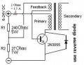
Here is the entire circuit. Except that I also put a 2 ohm 10 watt resistor on the positive supply wire for less abuse on the transistor.
You have to pay attention to the direction you wind the solid wire on the armature of the flyback or it won't work. Like the color picture. If it doesn't work just swap the wires on the feedback windings or rewind it the other direction.
This self oscillates and keeps making 3/8" sparks at a fairly high frequency.
I have made a few of these for a Jacobs Ladder and other projects.

That is thousands of volts and can be lethal.
DON'T LET IT BITE YOU!

Flyback 12v.jpg
2N3055 flyback driver.jpg
There are about 10 pins on the bottom of the flyback. When you get it working, hold the positive wire near those pins. Sparks will jump to the negative terminal. Solder your negative wire to that terminal, clip all the rest and cover them all with clear silicone glue.

Here is a video.

You do need a heat sink to keep the transistor cool. Don't let it touch anything but the transistor.
 
Last edited:

Thread Starter

Mellisa_K

Joined Apr 2, 2017
391
I got 10 flyback transformers on eBay for $25.00.
https://www.ebay.com.au/sch/i.html?...former.TRS0&_nkw=Flyback+Transformer&_sacat=0

You can get them from old TV sets or from a TV repair shop.
If you are not committed to the ignition coil, this is a great way to go.
Here is the entire circuit. Except that I also put a 2 ohm 10 watt resistor on the positive supply wire for less abuse on the transistor.
You have to pay attention to the direction you wind the solid wire on the armature of the flyback or it won't work. Like the color picture. If it doesn't work just swap the wires on the feedback windings or rewind it the other direction.
This self oscillates and keeps making 3/8" sparks at a fairly high frequency.
I have made a few of these for a Jacobs Ladder and other projects.

That is thousands of volts and can be lethal.
DON'T LET IT BITE YOU!

View attachment 155025
View attachment 155026
There are about 10 pins on the bottom of the flyback. When you get it working, hold the positive wire near those pins. Sparks will jump to the negative terminal. Solder your negative wire to that terminal, clip all the rest and cover them all with clear silicone glue.

Here is a video.

You do need a heat sink to keep the transistor cool. Don't let it touch anything but the transistor.
Sorry for delay.

Wow this is so very helpful of you. I really appreciate the trouble you've gone to. Thankyou.

I would prefer this solution than a bulky greasy auto coil.

And yes I will be careful.

Regards

M
 

MisterBill2

Joined Jan 23, 2018
27,980
There is a similar transformer used to trigger flash tubes in both stroboscopes and many photographic flash units. They produce a very high voltage but not much current. And the basic circuit will certainly work for ignition purposes, but you may need different parts. Also, check the "schematicsforfree" website. I think such circuits would be under "power ". or "photography", and possibly "lighting". But I know that they are there someplace.
 

Thread Starter

Mellisa_K

Joined Apr 2, 2017
391
There is a similar transformer used to trigger flash tubes in both stroboscopes and many photographic flash units. They produce a very high voltage but not much current. And the basic circuit will certainly work for ignition purposes, but you may need different parts. Also, check the "schematicsforfree" website. I think such circuits would be under "power ". or "photography", and possibly "lighting". But I know that they are there someplace.
Thanks for the tip.

I'm fascinated by the "schematics for free" website.

You AAC people are very helpful
 

MisterBill2

Joined Jan 23, 2018
27,980
In addition to everything else, probably there is no need for a heat sink on the transistor because when you light the burner it only takes a very few seconds if the spark gap is in the right location. Also, you do need to coordinate the turning on of the propane gas valve and pushing the button to operate the sparker circuit. It needs to be the opposite of match lighting, where you hold the match in place and then turn on the gas. Instead you turn on the gas valve and then push the sparker button, just like using a piezo igniter.
I suggest looking at a spark ignition system on either a gas grill or a gas stove with spark ignition in order to learn a bit about the actual operation. Nothing beats seeing a system work to provide inspiration as to how to duplicate the system.
 

Thread Starter

Mellisa_K

Joined Apr 2, 2017
391
In addition to everything else, probably there is no need for a heat sink on the transistor because when you light the burner it only takes a very few seconds if the spark gap is in the right location. Also, you do need to coordinate the turning on of the propane gas valve and pushing the button to operate the sparker circuit. It needs to be the opposite of match lighting, where you hold the match in place and then turn on the gas. Instead you turn on the gas valve and then push the sparker button, just like using a piezo igniter.
I suggest looking at a spark ignition system on either a gas grill or a gas stove with spark ignition in order to learn a bit about the actual operation. Nothing beats seeing a system work to provide inspiration as to how to duplicate the system.
Thankyou
Very sound advice
 
Top