IGBT module gate - Oscilloscope measuring

Thread Starter

Teris

Joined Nov 4, 2017
38
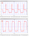
Hello, i am newbie to oscilloscope and i would like to measure with oscilloscope the gate of IGBT module. The manufacturer give the rights waveform as in the attached file.
I have set the oscilloscope in MATH functions (-) and i put the probes on GATE and EMMITER of IGBT, in order to see the waveform, but this is strong affected by the EMMITER - GROUND voltage.
How i can measure the GATE - EMMITER voltage right?
 

Attachments

Last edited:

DickCappels

Joined Aug 21, 2008
10,153
You can try a differential measurement using the scope's math function.
One probe goes on the emitter and the other on the gate.
The probes' ground clips go to ground somewhere other than the emitter.
Both channels of the scope should be set to the range, for example, 5 volts.
Set the scope to Channel 1 - Channel 2 and you can see the voltage difference between the gate and emitter.

That usually works for me.

Here is a demonstration:
 

AlbertHall

Joined Jun 4, 2014
12,345
You can try a differential measurement using the scope's math function.
One probe goes on the emitter and the other on the gate.
The probes' ground clips go to ground somewhere other than the emitter.
Both channels of the scope should be set to the range, for example, 5 volts.
Set the scope to Channel 1 - Channel 2 and you can see the voltage difference between the gate and emitter.

That usually works for me.

Here is a demonstration:
That works well providing the the voltage to ground does not overload the 'scope input.
 

Thread Starter

Teris

Joined Nov 4, 2017
38
The emmiter-ground voltage is about 150V and the bias signal of gate is PWM about 15V peak.
So the probe of channel 2 see the 150V. That's the problem.
 

AlbertHall

Joined Jun 4, 2014
12,345
Try AC coupling the two signals. You lose the DC information but you can still see the amplitude and waveform.
But then you will lose the math won't work as the two signals will lose their reference.

The best you can do with two standard probes is to display the two signals, DC coupled, as separate channels and set the amplitude (both channels the same) to display the two waveforms as large as will fit on the screen, then switch to dispay the difference between the two channels. The displayed waveform may not be very big though.
 

DickCappels

Joined Aug 21, 2008
10,153
Yes, I think that the waveform being too small is this person's issue.

The user can adjust the offset controls to get the waveform onto the screen with the loss of the DC component.
 
Top