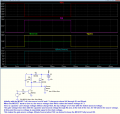
Igbt high side gate driver circuit
- Thread starter pon07023
- Start date
Scroll to continue with content
Hi ericgibbs.Hi pon.
Welcome to AAC.
You are using BJT transistor symbols, where is a Gate voltage?
E
The symbol on the rightmost side is igbt, and its gate voltage must be output as the sum of the collector voltage and the applied voltage, but it is output as the collector voltage.
ronsimpson
- Joined Oct 7, 2019
- 3,262
then How should I connect the bootstrap circuit?It you are trying to make a bootstrap driver, that's not a circuit to do that.
I anticipate that there will be many errors in the circuit due to my lack of conceptual knowledge in this area.
Last edited:
bypass capacitor :To rapidly charge and discharge the gate voltage of the IGBT.It is hard to understand with no voltages and no values of any kind.
There is a capacitor I don't understand. "why?"
View attachment 318969
The leftside input volts is 15V
the right side volts is 24V
So, I want to boost it to 39V, which is 15+25V, to control the IGBT.
I anticipate that there will be many errors in the circuit due to my lack of conceptual knowledge in this area.
ronsimpson
- Joined Oct 7, 2019
- 3,262
This is for educational purposes. Not trying to say the design is wrong. Learning!
-Capacitor "Why?" should go to ground.
-Holding the IGBT off: A1 is on and C=0.4 volts. Go up through a diode and we are at 1V. Q4 b-e gets us to 1.7V and Q5 adds more. The turn off voltage will be about +2.4V. Not good.
-Ron is the turn-on current to the Gate of IGBT. The current is probably small.
-Q3, Q4 have no real purpose.
-I cannot see how the Gate of IGBT can get above 16 volts.
-Do you need isolation? Q1?
What is the absolute mas Gate voltage for the IGBT? 20V?

Please answer these questions! It is hard to make a high side driver. Is it possible to move the load to +24 and have a low side driver?
Do you need isolation?
-Capacitor "Why?" should go to ground.
-Holding the IGBT off: A1 is on and C=0.4 volts. Go up through a diode and we are at 1V. Q4 b-e gets us to 1.7V and Q5 adds more. The turn off voltage will be about +2.4V. Not good.
-Ron is the turn-on current to the Gate of IGBT. The current is probably small.
-Q3, Q4 have no real purpose.
-I cannot see how the Gate of IGBT can get above 16 volts.
-Do you need isolation? Q1?
What is the absolute mas Gate voltage for the IGBT? 20V?

Please answer these questions! It is hard to make a high side driver. Is it possible to move the load to +24 and have a low side driver?
Do you need isolation?
ronsimpson
- Joined Oct 7, 2019
- 3,262
crutschow Good circuit. This is almost the same but with Q1,3 current amplifier. I normally drive MOSFETs and IGBTs very fast. If you are just looking for on/off and not PWM then use Crutschow's circuit.
In all cases you need to watch out for too much voltage on the Gate. (if using a 24V supply)

In all cases you need to watch out for too much voltage on the Gate. (if using a 24V supply)


