Identify component on Power Board

Thread Starter

isetlg

Joined Jan 12, 2024
12
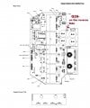
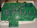
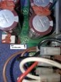
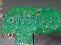
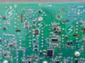
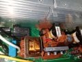
Please help identify the component located at Q26 of the 0558 102 426 PCB Power board assembly-CSA.
The component at Q26 has blown and the machine will not power up.
This board is from an ESAB EM215ic mig welder, it runs on 220 Volts or 110 v using Power cord adapter (120/230V), no switch.
On the circuit, Q26 is connected to 2 x 7w10kj cgs16.11 i believe are resistors.
Is this a DPAK mosfet ?,
The markings on my blown Q26 component is VNH19 ON 3N - ON is for Onsemi. Onsemi has no record of it. it measures 6 x 6 mm +-
A similar request for identification on the web has VNH11 ON 3N or an other has F50 ON 3N -could be a U.S. board.
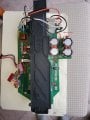
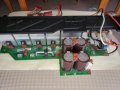
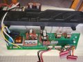
See pictures: 7W10KJ x2-to Q26-20240105_112217.jpg, 20240109_110823.jpg and Q26 to 7W10KJ-20240105_112320.jpg
Thank You .......


7W10KJ x2-to Q26-20240105_112217.jpg

Q26 to 7W10KJ-20240105_112320.jpg

VNH19 Onsemi.jpg
 

MisterBill2

Joined Jan 23, 2018
19,630
The blown apart device does appear to be a transistor of some type. The failure may have been caused by an external short circuit, a failed component, or possibly incorrect operation. Probably the device did not fail on it's own for no reason.
If you are able to contact the manufacturer of the welder there may be some help available. And if you have a circuit schematic for the welder or the circuit board that will help with locating the way to fix the welder.
 

Irving

Joined Jan 30, 2016
4,088
VNH19 is the manufacturing date code and is no help in identifying the device. It the other numbers that are needed..
 

Thread Starter

isetlg

Joined Jan 12, 2024
12
Thank you, all good suggestions.
I have contacted the manufacturer of the welder, ESAB, they are not willing to give the information.
Onsemi has replied positively saying that they have no record of number VNH19, so may well be the manufacturing date code.
I have found the service manual, esab_emp215ic_ems215ic_multi_process_welder.pdf,
and it contains a few circuit schematics- i have posted a few here.
 

Attachments

MisterBill2

Joined Jan 23, 2018
19,630
OK, there is a circuit schematic of the circuit board, a paarts layout, and an interconnect drawing. So it should be possible to find the part number.and also see what caused the part to fail.
 

Irving

Joined Jan 30, 2016
4,088
Unfortunately the info needed isn't in any of those pages. This device would appear to be, based on location, part of the PFC boost control inside the box on the 1st schematic, but, hving looked through the whole manual at manuals.lib there's no useful info in the remaining pages... The main PCB is a non-servicable item - if its faulty you replace the whole PCB, no board level repair info is given.

Its also a fair bet that a catastrophic failure like that isn't the only fault on the board - replacing it without a full investigation is likely to end up with the new part destroyed and/or further damage to the board. Fault finding on a board running with 400v DC requires specialist tools and knowledge - you can easily destroy your test equipment and/or yourself.


1705748217866.png
 

Pyrex

Joined Feb 16, 2022
315
I suggest to desolder those two 7W resistors and draw a piece of circuit diagram related to the Q26 from the PCB. It seems only a couple connections from the Q26.

Imho, it's some kind of discharge of those big 470uF 500V capacitors
 

MisterBill2

Joined Jan 23, 2018
19,630
Given the excellent photo in post #1 showing the failed part and a bit of the surrounding PCB, we should be able to have a photo showing both sides of the PCB with about twice the area of PCB included, so that the circuit associated with the Q26 can be determined and evaluated. There might even be enough information to determine what part of the system function Q26 was part of, which might even help determine the cause of the failure.
 

Irving

Joined Jan 30, 2016
4,088
Its power factor correction. The welder looks highly inductive to the incoming AC, so by actively adding capacitance in a controlled manner during the AC cycle, the whole unit be made to look more resistive and more friendly to the mains. But its unlikely the PFC caused Q26 to explode. Its been overloaded way outside its expected Safe Operating Area. One possibility is that there are shorted turns internally on one or other of the inverter transformers and its was trying to correct for that.

It'll be associated with an PFC IC - here is an example circuit (from this document) the Q26 is possibly the MOSFET shown here.. though the welder shows Q19/21 IGBTs as the boost devices, so maybe Q26 is associated with driving them...

1705754961193.png
 

Irving

Joined Jan 30, 2016
4,088
If we could get some good hi-res photos of the whole board from vertically above both sides it may be possible to work out what the actual purpose of Q26 is and a test strategy...
 

MisterBill2

Joined Jan 23, 2018
19,630
Thanks to Irving for the excellent schematic diagram. Based on that the only suspect component would be the contacts on the relay shunting the NTC resistor. If those contacts have welded closed that could cause a problem.
Or the diagnosis given in post #10 may be the cause.
Only testing that relay would be a simple check, which I suggest doing.
 

Irving

Joined Jan 30, 2016
4,088
Hmmm, well this is the best I can do from those pics...

Its not making a great deal of sense to me.

Two key questions I can't easily tell from those pics:
1. where does that red via on the top of the board is go (from the MOSFET gate)?
2. Does either side of the two white 10k resistors connect to something else, eg +, on the top of the board


1706470370588.png


1706471016707.png
 

Thread Starter

isetlg

Joined Jan 12, 2024
12
Hello Irving


i have removed and checked the 2 10k resistors, they are good and there is nothing else connected to them.


a fellow locally suggested to try a FDD5N50NZTM – N-Channel 500 V 4A (Tc) 62W (Tc) Surface Mount TO-252AA from onsemi.


so i did, the machine power up for a second, lights and leds, turns on and off, tries to turn on 3 times , then nothing.


after a few minutes same thing. most likely something else is bad,


Will start testing major components as per manual, might take me a while, not my area of comfort.


I really appreciate your input, thanks
 

Irving

Joined Jan 30, 2016
4,088
i have removed and checked the 2 10k resistors, they are good and there is nothing else connected to them.
Are they connected to the + side of the capacitors or not?

Did you find where that 'via' from the MOSFET gate goes to?

That snippet of circuit I drew must connect to something else to be useful....
 
A couple questions for isetlg. I have that exact same welder with a blown component that looks exactly like the one you blew but in a different location. was the component FDD5N50NZTM the correct component? and did you have any luck on getting your welder back working? what was wrong if you got it fixed? Thanks
 

Irving

Joined Jan 30, 2016
4,088
A couple questions for isetlg. I have that exact same welder with a blown component that looks exactly like the one you blew but in a different location. was the component FDD5N50NZTM the correct component? and did you have any luck on getting your welder back working? what was wrong if you got it fixed? Thanks
Hi @wandering909, Welcome to AAC!

1. Can you confirm that the component at Q26 on your welder is the FDD5N50NZTM?

2. What part has failed on your welder? Q??

3. What were you doing when it failed? (@isetlg same question?)
 
Hello Irving, thanks for the reply,
1) No, I can not confirm that Q26 is FDD5N50NZTM. However from looking at my board, I think Q26 could be some type of igbt transistor. There are other igbt transistors with factory markings on them also labeled with the "Q" identifier.
isetlg, look at the transistors that are attached to the big heatsink near the center of the board. Most are labeled as "Q" with a number. Q6 for example, part number is GW60V60DF. I googled their part numbers and they came back as IGBT transistors. Although this isn't the part you need it might help narrow your search into the igbt type. I am very novice so i could be wrong about these assumptions. Hopefully this will help you out.
https://www.mouser.com/datasheet/2/389/stgw60v60df-1850726.pdf

2) The part that failed on my board is D72 which I think could be a rectifier. There are two large rectifiers behind the large brown capacitors that are labeled D49 and D50 which have labeling and are rectifiers from the research that I have done.
3) I turned the unit on and the part blew immediately.

D72, my broken part, is connected to a film capacitor on one side and a transformer on the other. I included a picture of the transformer and capacitor with a red line showing what my broken part connects to.
 

Attachments

Top