I'd like to hack this..

Thread Starter

DR1

Joined Sep 13, 2012
23
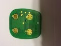
I have a backup keyfob for my car I'd like to hack. I know the rules on car projects so I'll keep this about electronics. I took out the circuit board for the fob and I'd like to add an Attiny85 for control. The key fob has 4 buttons, I'll just be working with 2. Here's a pic of the board. After connecting both grounds, would I just have to solder leads to the + of each button going to a pin on the attiny? Then, by sending that pin high, it would mimic the button being pressed. Am I going about this the right way?
 

Attachments

Last edited:

THE_RB

Joined Feb 11, 2008
5,438
I'm not sure if this will be closed down by the moderators as an "automotive modification". Technically it seems to be an external accessory, not part of the car but that's just my personal opinion.

Regarding your question, all 4 contact sets have one side connected to the ground plane, so it is not using matrixed keys, just simple "connect to ground when pressed" type keys.

That is common in these type devices as the keys connect directly to the micro's pins, and use the microcontroller's internal pullup resistors on the pins.

So assuming that is true you can easily connect the 4 keys to 4 output pins on your ATtiny, but both circuits need to have the grounds connected too.

I would use 4 resistors to connect them, a value of 270 ohms should be fine and give some protection against shorts etc.
 

Thread Starter

DR1

Joined Sep 13, 2012
23
Hello RB, thanks for the reply. Seems like this shouldnt be too hard of a project. One part Im stuck on, Im using a dev board which uses 5V logic. Would I need something to first drop to 3V, then add a 270 ohm resistor?
 

alexfreed

Joined Oct 8, 2012
72
No. You can configure the uC pins to be outputs set to 0 when active and high-Z when not, essentially emulating open collector. Or use actual open collector/drain buffers to make the program simpler.
 

GopherT

Joined Nov 23, 2012
8,009
You can also use an analog switch IC (CD4066, or 74HC4066), the switch will simply connect any two pins when a third pin is driven high, disconnect when the third pin is low. A single IC will have 4 switches on it.
 

THE_RB

Joined Feb 11, 2008
5,438
There are a couple of other methods, you can use a two resistor voltage divider on each 5v output pin. Since you already plan to use a 270 ohm series resistor to connect to the keypads, just put a 470 ohm resistor from each keypad to ground. That will give you about 3.2v as your HI level.

Another way is to use a series diode on each pin, this will act something like the open-drain (open-collector) output that Alexfreed mentioned.
 

Austin Clark

Joined Dec 28, 2011
412
Uhm, why not just use a simple NPN transistor to pull down the pad to ground when the microcontroller pin goes HIGH? It would literally require a single resistor and transistor, both very tiny and cheap.
 

BobTPH

Joined Jun 5, 2013
11,515
Why? The microcontroller can just as well pull it low itself, as suggested previously with no additional components.

Bob
 

Austin Clark

Joined Dec 28, 2011
412
Why? The microcontroller can just as well pull it low itself, as suggested previously with no additional components.

Bob
Good point, that's much better, if the micro must be cable of such a configuration and sinking enough current, which it more than likely is.
You could use the pins signals in multiple places if you used a transistor though I suppose. That idea slipped my mind after having read it, I was mainly responding to the later suggestions that seemed needlessly complex to me.
 

THE_RB

Joined Feb 11, 2008
5,438
It's a good suggestion for some apps, it definitely gives the open-collector (switched pulldown) capability.

If you used NFETs instead of NPN transistors, you don't even need the base resistor as the FET gate can be driven driect from the micro's output pin.
 

Thread Starter

DR1

Joined Sep 13, 2012
23
So Im stuck. Im having a problem with the connection. Im using an Arduino Uno for this project atm. I made the voltage divider and its putting out 3.15V. I used the 5v pin on the Arduino and tested with a multimeter. Works. But when I replace that 5V wire with the I/O pin Im using and send that pin HIGH, it only shows .05V rather than the 3.15V. Im confused.
 

Kermit2

Joined Feb 5, 2010
4,162
If one side of the switch is ground, then most likely it operates on a NEGATIVE going pulse edge. Holding the key down would GROUND that signal line. The micro should be programmed to send a 0 volt output pulse.
 

Thread Starter

DR1

Joined Sep 13, 2012
23
I took the fob out of the circuit for now, til I get this problem fixed. I get 5v out of the 5V pin and 4.8V out the I/O when pulled HIGH. The 5V pin though can supply max 500mA. The I/O pins have a max of 40mA. Like I stated, the voltage divider works fine with the 5v pin, so has to be difference in current. Not sure how exactly to go about fixing it.

I have a couple N Channel mosfets, would I be able to attach the I/O pin to the gate then use the 3.3v on the Drain. Ground to Source?
 

GopherT

Joined Nov 23, 2012
8,009
I took the fob out of the circuit for now, til I get this problem fixed. I get 5v out of the 5V pin and 4.8V out the I/O when pulled HIGH. The 5V pin though can supply max 500mA. The I/O pins have a max of 40mA. Like I stated, the voltage divider works fine with the 5v pin, so has to be difference in current. Not sure how exactly to go about fixing it.

I have a couple N Channel mosfets, would I be able to attach the I/O pin to the gate then use the 3.3v on the Drain. Ground to Source?
I think it is time to post a schematic, I'm lost.
 

KMoffett

Joined Dec 19, 2007
2,918
Used CD4066 analog switches many years ago to start and stop several stopwatches. Just wire them in parallel with the stopwatches' switch contacts.

Ken
 
Top