Facebook
 Google
 GitHub
 Linkedin
Hi team, here I have a remote operated ceiling fan, which I would like to add manual control. This is the unit, the lower connectors in pic 1 are, on the right hand side, 3 wire to the motor and 2 wire to the light.
The left hand connector the AC power input, Live, Neutral, Earth.
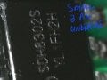
At the top are two other unused connectors, a small white 2 pin unit and the black one to the upper left which has 6 pins. These are close to the radio receiver board and am hoping are connected to the receiver some how...
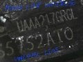
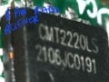
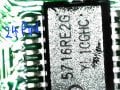
I have tried searching some of the chip numbers and such, as well as searching for a circuit diagram and found only Chinese pages relating to the chips, and other makes of fans seemingly using similar boards and features.
Is it even possible to decipher the board and add the manual control of some sort.

The left hand connector the AC power input, Live, Neutral, Earth.
At the top are two other unused connectors, a small white 2 pin unit and the black one to the upper left which has 6 pins. These are close to the radio receiver board and am hoping are connected to the receiver some how...
I have tried searching some of the chip numbers and such, as well as searching for a circuit diagram and found only Chinese pages relating to the chips, and other makes of fans seemingly using similar boards and features.
Is it even possible to decipher the board and add the manual control of some sort.