 Facebook
 Google
 GitHub
 Linkedin
Hello All
I am a novice at this and I just built a door alarm using a kit. This is the kit schematic:

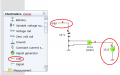
I built it and it works fine, but I want to analyze the circuit using sim software (Yenka). So this is the sim version I did:

When I close the first switch (S1) in the sim above the alarm sounds but IC1d and IC1a blow up (they are pins on an IC4093). The error I get is:

I don't know what I am missing here. I have checked the circuit and cannot see the problem. The only odd thing is that the kit schematic requires a BC328 PNP transistor shown as Q1. The sim software doesn't have a BC328 transistor so I selected a BC178 and changed the ratings to match what I think mimics the BC328:

So could this be the problem, being that the sim software does not have the required transistor. Or, if the ratings I used on the BC178 actually do the same as a BC328 then I am completely lost as to why IC1d and IC1a blow up.
If it is the transistor these are the only choices the sim software provides for PNP transistors:

They seem to be a limited set of choices but I assume you can modify the ratings to get the desired transistor, but I am only guessing.
Any help appreciated. Is it how I have setup the transistor, or is there another problem in the sim circuit?
I am a novice at this and I just built a door alarm using a kit. This is the kit schematic:
I built it and it works fine, but I want to analyze the circuit using sim software (Yenka). So this is the sim version I did:
When I close the first switch (S1) in the sim above the alarm sounds but IC1d and IC1a blow up (they are pins on an IC4093). The error I get is:
I don't know what I am missing here. I have checked the circuit and cannot see the problem. The only odd thing is that the kit schematic requires a BC328 PNP transistor shown as Q1. The sim software doesn't have a BC328 transistor so I selected a BC178 and changed the ratings to match what I think mimics the BC328:
So could this be the problem, being that the sim software does not have the required transistor. Or, if the ratings I used on the BC178 actually do the same as a BC328 then I am completely lost as to why IC1d and IC1a blow up.
If it is the transistor these are the only choices the sim software provides for PNP transistors:
They seem to be a limited set of choices but I assume you can modify the ratings to get the desired transistor, but I am only guessing.
Any help appreciated. Is it how I have setup the transistor, or is there another problem in the sim circuit?
")


