I want to glow LED clusters in series one by one without programming....

Thread Starter

Ishan Jain

Joined Nov 12, 2016
100
Hello folks!

Basically what I want to do is I have a single LED following that is a group of 3 LED's and then a group of 9 LED's. So I want that when I press the switch the single LED glows then after some time the group of 3 LED's glow and then the group of 9 LED's glow. How can I achieve this without programming?
 

WBahn

Joined Mar 31, 2012
32,970
Hello folks!

Basically what I want to do is I have a single LED following that is a group of 3 LED's and then a group of 9 LED's. So I want that when I press the switch the single LED glows then after some time the group of 3 LED's glow and then the group of 9 LED's glow. How can I achieve this without programming?
There are a number of ways to do it. You can use a circuit based on two or three 555 timers. You could use a circuit based on a simple state machine. You could use a circuit based on a ramp generator and window comparators. You could achieve this with relays and RC delay elements.

You need to be clearer (more complete) in your description, though. For instance, once an LED turns on, does it stay one even after the next cluster lights up? If not, is there a delay between when one cluster goes off and the next comes on? Also, after the last cluster comes on does it automatically shut off at some point? Or does it require a separate signal to reset the system? Also, what are the time scales involved? Is "after some time" measured in milliseconds, seconds, minutes, weeks?
 

Thread Starter

Ishan Jain

Joined Nov 12, 2016
100
There are a number of ways to do it. You can use a circuit based on two or three 555 timers. You could use a circuit based on a simple state machine. You could use a circuit based on a ramp generator and window comparators. You could achieve this with relays and RC delay elements.

You need to be clearer (more complete) in your description, though. For instance, once an LED turns on, does it stay one even after the next cluster lights up? If not, is there a delay between when one cluster goes off and the next comes on? Also, after the last cluster comes on does it automatically shut off at some point? Or does it require a separate signal to reset the system? Also, what are the time scales involved? Is "after some time" measured in milliseconds, seconds, minutes, weeks?
Yes I want time delay between two clusters and also when the latter one is illuminated the former one shuts off. The delay should be around 1 second and after the last clusters comes on the whole system should shut off. Please provide me the circuit for this, its kinda urgent.
 

WBahn

Joined Mar 31, 2012
32,970
Yes I want time delay between two clusters and also when the latter one is illuminated the former one shuts off. The delay should be around 1 second and after the last clusters comes on the whole system should shut off. Please provide me the circuit for this, its kinda urgent.
How urgent? When is the assignment due?
 

absf

Joined Dec 29, 2010
1,968
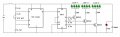
The clock from 555 could be stopped either by pulling the "Reset" pin of 555 low or making the "EN" pin of 4017 high.

It's up to the TS to decide. But if he comes back and asks. We would be sure to help. :D;)

Allen
 

Thread Starter

Ishan Jain

Joined Nov 12, 2016
100
The clock from 555 could be stopped either by pulling the "Reset" pin of 555 low or making the "EN" pin of 4017 high.

It's up to the TS to decide. But if he comes back and asks. We would be sure to help. :D;)

Allen
Thanks a lot for the circuit :). According to Reloadron's modification of the decade counter is required in order to stop the process and then again start it with a push or reset button. So Is there any requirement of such modification?
 

Reloadron

Joined Jan 15, 2015
7,893
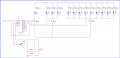
Here is a rough sketch. 4017 Run to Halt.png
I have omitted the LED series resistor values. Once the LED data sheet Vf and If are known they can be worked out. The circuit needs a clock signal in, likely a 555 will do fine. The switch is an On- Off Center-Momentary with the MM position used for reset and On is run. LED timing is a function of the clock source.

Ron
 

Thread Starter

Ishan Jain

Joined Nov 12, 2016
100
Here is a rough sketch. View attachment 123219
I have omitted the LED series resistor values. Once the LED data sheet Vf and If are known they can be worked out. The circuit needs a clock signal in, likely a 555 will do fine. The switch is an On- Off Center-Momentary with the MM position used for reset and On is run. LED timing is a function of the clock source.

Ron
I am not getting the switch arrangement you have done here and whether the type of switch you have quoted here is same as the switch you used in the circuit diagram and how will the switch work in this circuit?
 

Reloadron

Joined Jan 15, 2015
7,893
The switch is a SPDT switch but rather than On-Off-On with a center off the switch is a Mom-Off-On with Mom being a spring loaded momentary. Here is an example of the switch type. The switch Common goes to the 4017 RST (Reset) pin. Placing RST at Ground potential enables the 4017 chip to run. Thus I use the switch On position. Placing the 4017 RST pin at Logic High resets the count. Thus I used the Mom (Momentary) of a switch. The switch is a very common type switch. There are 3 positions with an Off center. The link is just a basic example. You can choose the mount you want. I used a basic panel mount toggle as an example.

I also omitted the 2N2222 base resistors as that will depend on the maximum current load for each transistor which is a function of the Ifwd current of the LEDs you choose.. I also gave each LED its own resistor in series. No two LEDs are identical, since the LED is current driven it is good practice to afford each LED its own series resistor. Even within the same part number one LED will draw more or less current than the one beside it. Thus, good practice id each LED has its own current limiting resistor.

Ron
 

Thread Starter

Ishan Jain

Joined Nov 12, 2016
100
The switch is a SPDT switch but rather than On-Off-On with a center off the switch is a Mom-Off-On with Mom being a spring loaded momentary. Here is an example of the switch type. The switch Common goes to the 4017 RST (Reset) pin. Placing RST at Ground potential enables the 4017 chip to run. Thus I use the switch On position. Placing the 4017 RST pin at Logic High resets the count. Thus I used the Mom (Momentary) of a switch. The switch is a very common type switch. There are 3 positions with an Off center. The link is just a basic example. You can choose the mount you want. I used a basic panel mount toggle as an example.

I also omitted the 2N2222 base resistors as that will depend on the maximum current load for each transistor which is a function of the Ifwd current of the LEDs you choose.. I also gave each LED its own resistor in series. No two LEDs are identical, since the LED is current driven it is good practice to afford each LED its own series resistor. Even within the same part number one LED will draw more or less current than the one beside it. Thus, good practice id each LED has its own current limiting resistor.

Ron
Thanks a lot Ron, circuit is working properly after simulation. Now I understood the use of a SPDT switch in this circuit. Thank you :D:)
 
Top