Facebook
 Google
 GitHub
 Linkedin


panic mode
- Joined Oct 10, 2011
- 5,421
you misunderstood me. i have to deal with a lot of data, and different disciplines. i cannot possibly memorize everything, and sometimes my recollection may be flawed, plus i get frequent distractions so i suggest checking resources yourself is always a good idea. after all why would you take at face value anything told by a stranger? you need to do your own evaluation of everything you find on internet.
in this case conversation touched on 555 chip - something i have of course used but not recently. so initial comment about duty cycle was wrong (based on my rusty recollection) as i did not have time to lookup any of the resources like:
https://www.allaboutcircuits.com/tools/555-timer-astable-circuit/
as the saying goes, all solutions are cheap, fast and good - pick any two.
there you can see how to calculate frequency and duty cycle.
if you want to drive MOSFET directly from 555 output, you need to get the same frequency and duty cycle without inverting that is done by Q1.
btw, i see no reason to use R5/R6 divider if supply is 9-12VDC and Vgs can be up to 20V.
but if you want to eliminate Q1 and surrounding resistors, you need to do some sanity checks.
link above shows how to calculate things:
T=0.694(R1+2*R2)C
T1=0.694(R1+R2)C
Duty Cycle = 100* T1/T
Duty Cycle = 100*(R1+R2)/(R1+2*R2)
so what values of R1 and R2 are needed to keep 140Hz and 2% duty cycle?
f=1.44/((R1+2*R2)*C) = 140
2=100*(R1+R2)/(R1+2*R2)
doing the math on later equation yields:
R1+2*R2 = 50*R1+50*R2
0=49*R1+48*R2
R2/R1=-49/48
as you can see there is a negative sign so this is not going to work.
so if you want to remove Q1 and drive mosfet directly, oscillator circuit would need to be modified. that circuit cannot get low duty cycle (which is why Q1 was there).
so for that one would need to use diodes to independently control on/off periods as shown here:
https://www.electronics-tutorials.ws/waveforms/555_oscillator.html
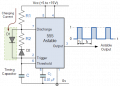
so now, instead of t1= 0.693(R1 +R2) x C, on-time is just t1=0.693(R1 x C)
and t2=0.693(R2 x C).
T=t1+t2 = 1/140Hz = 7.143ms
and R1 must be less than R2. in fact t1/t2=R1/R2=0.02 (2percent)
so R2=50*R1 and t2=50*t1
etc.
t1+50*t1=7.143ms means t1=7.143ms/51=0.14ms and t2=7.003ms
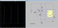
so reducing capacitor from 100nF to 10nF I get R1=2020 Ohm and R2=101kOhm, those can be rounded to nearest common values.
but... don't quote me on that, do your own calculation or simulation. this was illustration of one approach. btw the equations are not exactly correct. they are (reasonable) approximations. and diodes are not ideal either...
so trying to let you use same parts as before, this seem to get right timing:
in this case conversation touched on 555 chip - something i have of course used but not recently. so initial comment about duty cycle was wrong (based on my rusty recollection) as i did not have time to lookup any of the resources like:
https://www.allaboutcircuits.com/tools/555-timer-astable-circuit/
as the saying goes, all solutions are cheap, fast and good - pick any two.
there you can see how to calculate frequency and duty cycle.
if you want to drive MOSFET directly from 555 output, you need to get the same frequency and duty cycle without inverting that is done by Q1.
btw, i see no reason to use R5/R6 divider if supply is 9-12VDC and Vgs can be up to 20V.
but if you want to eliminate Q1 and surrounding resistors, you need to do some sanity checks.
link above shows how to calculate things:
T=0.694(R1+2*R2)C
T1=0.694(R1+R2)C
Duty Cycle = 100* T1/T
Duty Cycle = 100*(R1+R2)/(R1+2*R2)
so what values of R1 and R2 are needed to keep 140Hz and 2% duty cycle?
f=1.44/((R1+2*R2)*C) = 140
2=100*(R1+R2)/(R1+2*R2)
doing the math on later equation yields:
R1+2*R2 = 50*R1+50*R2
0=49*R1+48*R2
R2/R1=-49/48
as you can see there is a negative sign so this is not going to work.
so if you want to remove Q1 and drive mosfet directly, oscillator circuit would need to be modified. that circuit cannot get low duty cycle (which is why Q1 was there).
so for that one would need to use diodes to independently control on/off periods as shown here:
https://www.electronics-tutorials.ws/waveforms/555_oscillator.html
so now, instead of t1= 0.693(R1 +R2) x C, on-time is just t1=0.693(R1 x C)
and t2=0.693(R2 x C).
T=t1+t2 = 1/140Hz = 7.143ms
and R1 must be less than R2. in fact t1/t2=R1/R2=0.02 (2percent)
so R2=50*R1 and t2=50*t1
etc.
t1+50*t1=7.143ms means t1=7.143ms/51=0.14ms and t2=7.003ms
so reducing capacitor from 100nF to 10nF I get R1=2020 Ohm and R2=101kOhm, those can be rounded to nearest common values.
but... don't quote me on that, do your own calculation or simulation. this was illustration of one approach. btw the equations are not exactly correct. they are (reasonable) approximations. and diodes are not ideal either...
so trying to let you use same parts as before, this seem to get right timing:
Last edited: