I really Need Help With this Circuit (Full Cycle Alarm and CLock)

Thread Starter

TracyThao

Joined Aug 11, 2024
13
Hi guys,
I am very new with this forum and i heard there are a lot of expert in this forum.
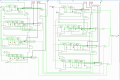
i am currently build a full clock and alarm circuit. And i need you guys help me have a look this circuit and
Please tell me why :
* the AM/PM lead on the Alarm side is not working.
*The out put lead on the left side should be off when the clock match with the alarm, Why it still on all the time.
Did i do something wrong with the circuit on the Alarm side.
 

Attachments

dl324

Joined Mar 30, 2015
18,216
Welcome to AAC!

What simulator are you using?

Is this really homework? I started to respond to your other thread in Digital Design.

It would be helpful if you used some hierarchy in your circuit, avoided unnecessary wire jogs and scenic routing, and turned off the grid.
 

Thread Starter

TracyThao

Joined Aug 11, 2024
13
Welcome to AAC!

What simulator are you using?

Is this really homework? I started to respond to your other thread in Digital Design.

It would be helpful if you used some hierarchy in your circuit, avoided unnecessary wire jogs and scenic routing, and turned off the grid.
I am using Logisim as a simulator.
 

dl324

Joined Mar 30, 2015
18,216
I am using Logisim as a simulator.
What version are you using? Version 2.7.1 doesn't have the TTL library you're using.

You shouldn't do things like this:
wiringIssues.jpg
You shouldn't put wires on top of symbols. The wiring for the AND gate makes it extraneous.
 

dl324

Joined Mar 30, 2015
18,216
Do you think you can help me completely correct my circuit please.
If you can tell me where to download the version of Logisim you're using, I might be able to help you in time. For schoolwork, we only give hints, so progress is at your speed. When is the assignment due?

Why are you using asynchronous counters? They can cause problems (glitches) decoding the outputs.
 

Thread Starter

TracyThao

Joined Aug 11, 2024
13
If you can tell me where to download the version of Logisim you're using, I might be able to help you in time. For schoolwork, we only give hints, so progress is at your speed. When is the assignment due?

Why are you using asynchronous counters? They can cause problems (glitches) decoding the outputs.
Hi Denis.
This is the link for Logisim 3.8.0
https://github.com/logisim-evolutio...wnload/v3.8.0/logisim-evolution-3.8.0-x86.msi
It is due by this Sunday 18/8.
The reason why i am using asynchronous counters is that i had taught so far. -.-
 

Attachments

dl324

Joined Mar 30, 2015
18,216
This is the link for Logisim 3.8.0
Thanks. I installed it and can view your design.

You should go back and read the last section of the instructions about making your work readable. Your work isn't readable.

It's going to take me time to follow your circuit because it's so spread out and you didn't use hierarchy as was suggested in the instructions.

You also didn't keep the controls together to make it easier to use them.
 

dl324

Joined Mar 30, 2015
18,216
Did i do something wrong with the circuit on the Alarm side.
Your method for comparing the two times is wrong.

You haven't implemented a 12-hour clock as required in the instructions. While you're doing that, I suggest that you work on adding hierarchy to improve readability of your circuit.
 
Last edited:

dl324

Joined Mar 30, 2015
18,216
The out put lead on the left side should be off when the clock match with the alarm, Why it still on all the time.
I see that you're checking the thread, but not responding or posting your latest work. You're running out of time and you haven't implemented the hours correctly. It's supposed to count from 1-12, not 0-19.

Regarding why the alarm indicator is always on. Think about what you need to do and compare that with what you've actually done. Your implementation will give an alarm indication if a bit on any counter is HIGH.

If you're confused, say so and members can offer guidance.
 

Thread Starter

TracyThao

Joined Aug 11, 2024
13
I see that you're checking the thread, but not responding or posting your latest work. You're running out of time and you haven't implemented the hours correctly. It's supposed to count from 1-12, not 0-19.

Regarding why the alarm indicator is always on. Think about what you need to do and compare that with what you've actually done. Your implementation will give an alarm indication if a bit on any counter is HIGH.

If you're confused, say so and members can offer guidance.
Thank Dennis.
I having a tutorial on wendesday and Thursday.
I just have time now to fix my stage 5. will post to you soon
 

Thread Starter

TracyThao

Joined Aug 11, 2024
13
I have been fix the clock to 12 hours mode now.
My question is what gate should i used to connect the clock and alarm together. So when i set the alarm mode to certain time. The out put lead will be on when the clock timer hit the same time as alarm time.
Thank you Dennis.
Tracy regard.
 

dl324

Joined Mar 30, 2015
18,216
I have been fix the clock to 12 hours mode now.
You haven't fixed it. It's supposed to count from 1-12 and yours counts from 0-12.

Also, you have the display bus for the H1 clock counter shorted to the alarm. With that short, the hours counter can't work. I had to remove the short before I could verify whether you had implemented the hours counter correctly.
My question is what gate should i used to connect the clock and alarm together.
You want to get an output when the times indicated on the counters are the same. What type of gate would give you a HIGH (or LOW) output when both inputs are the same?
 

Thread Starter

TracyThao

Joined Aug 11, 2024
13
You want to get an output when the times indicated on the counters are the same. What type of gate would give you a HIGH (or LOW) output when both inputs are the same?
[/QUOTE]
To enable the alarm i think using AND gate.
to Disabling the alarm and resuming Clock , i think using of OR gate.
And using Not gate for pausing the clock in the set alarm mode.
 

Thread Starter

TracyThao

Joined Aug 11, 2024
13
You want to get an output when the times indicated on the counters are the same. What type of gate would give you a HIGH (or LOW) output when both inputs are the same?
To enable the alarm i think using AND gate.
to Disabling the alarm and resuming Clock , i think using of OR gate.
And using Not gate for pausing the clock in the set alarm mode.
[/QUOTE]

But to implemented with the circuit i don't know how. Can you help me connected to it together please.
Please Disregard the mistake for counting 0-12
 

dl324

Joined Mar 30, 2015
18,216
Can you help me connected to it together please.
I can only offer suggestions because this is schoolwork for which you will be given credit.

I already gave you a big hint on how to implement the time comparison by telling you that it can be done with a single logic gate (with more to combine the output from the 4 counters and AM/PM indicator).
Please Disregard the mistake for counting 0-12
You're giving up 5 points by not implementing 1-12.

You're also giving up points for using two separate displays and not being neat.
 
Top