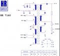
The primary is the top left winding, terminals #8 and #9
There is no "ground" terminal, but there are a few terminals tied to the common, #3, #5, and#10. I hope that answers your concern, which we have no clue as to what the concern is.
Note that the reason for defining those connections as "the primary" is that it is the only one showing a power input to the transformer. The fact is that a "Primary" winding must be physically able to impart enough energy into the core to supply the requirements of all of the "secondary" windings.
The circuit around the transformer points toward it being part of a CRT type display system. So I am very much wondering about the possible alternative application that it is intended for.
That might be quite interesting to a few of us.
The primary is the top left winding, terminals #8 and #9
There is no "ground" terminal, but there are a few terminals tied to the common, #3, #5, and#10. I hope that answers your concern, which we have no clue as to what the concern is.
Note that the reason for defining those connections as "the primary" is that it is the only one showing a power input to the transformer. The fact is that a "Primary" winding must be physically able to impart enough energy into the core to supply the requirements of all of the "secondary" windings.
This Transformer was taken from a TV, or other CRT application,
and it was designed specifically to suit that application,
and it very likely has the bare minimum specifications for that particular application.
If the idea is to use this Transformer for a heavy-Flyback-Power-Supply application, it probably won't work at all.
If You will explain what your end-goal is, you will probably get some excellent and valuable advice.
.
.
.
On your transformer, I would use pins 7 and 11 as the negative side of the output. (Connect them to ground.)
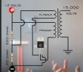
It looks like he has more voltage that the transformer was rated for.
On your transformer, I would use pins 7 and 11 as the negative side of the output. (Connect them to ground.)
It looks like he has more voltage that the transformer was rated for. View attachment 329691
It does not appear that this transformer application utilizes a feedback coil, as it does not appear to be part of an oscillator arrangement. quite probably it is a driven circuit, not an oscillator, which we could verify if we had seen more of the circuit.
So now I am asking about what is the purpose of the question and what benefit to the TS is anticipated for the correct answer to provide??? Many participants are quite happy to provide information, and also able to provide a fair amount of insight, given clues as to what may be a benefit to the TS.
Probably the portion of the transformer between terminals #3 and #4 can serve as al feedback source. Which polarity will work may need some experimenting. And definitely a series resistor to limit the base current.
ALSO, given that have no information as to the power supply voltage identified only as "Vcc" on the drawing, we have no way of recommending what voltage to operate the circuit at. It may be that others are more familiar with the original system, or that parts of the drawing we are not allowed to see will provide some useful information in that regard.
Good Luck!
This transformer was designed to drive a large capacitor. Some transformers have capacitors inside. Yours does not show caps but may have them. I don't know. Using pin 7 gives you a bleader resistor to discharge the capacitor(s). It costs you nothing to connect it.
Agree with MIsterBill2 about #3-4. The transformer was not designed for this job but may work.
Probably the portion of the transformer between terminals #3 and #4 can serve as al feedback source. Which polarity will work may need some experimenting. And definitely a series resistor to limit the base current.
ALSO, given that have no information as to the power supply voltage identified only as "Vcc" on the drawing, we have no way of recommending what voltage to operate the circuit at. It may be that others are more familiar with the original system, or that parts of the drawing we are not allowed to see will provide some useful information in that regard.
Good Luck!
.
You don't need anyone's permission to "try" something.
Nobody knows whether or not your Transformer will be compatible with your provided Circuit.
Maybe it will do something, and maybe it won't.
Getting it to work may be a real challenge.
.
.
.
A feedback signal needs a reference, which in this case would be the other end of that winding, which I think is terminal 3. So in post #12 that coil tagged as "flyback" would be terminals #3 and #4, more commonly called the "feedback" portion of the circuit.
 Facebook
 Google
 GitHub
 Linkedin
 152 KB Views: 38