 Facebook
 Google
 GitHub
 Linkedin
I have an e scooter that I use in an area that has a 20 degree incline as part of it. The scooters top speed is 15mph on flat ground, but only 7mph on this incline.
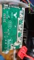
The battery is a 36v battery (red/black wires) and the motor controller has 6 FET transistors (see pics) that share a common bus bar for positive power and grounding is done through the frame I believe.
I believe there are 3 (green/blue/yellow wires) wires that are + output wires of 18vDc out that correspond to the low/medium/high ranges of the scooter and each FET is paired with another FET, as it appears the speed of the unit is adjusted by controlling the amperage flow. Total amperage rating for the scooter brushless motor controller is 13A.
I considered trying to duplicate the controllers setup with an additional 2 FET transistors for a boost when I needed it going up hills, but maybe I could take a momentary contact switch and a resistor ladder to get the 18v as well as control current and do the same thing more simply?
Has anyone done this, or can you at least confirm whether that's a suitable plan or not? A crude drawing is below, the red wiring that goes to the (2) 5ohm resistors and SPST switch on down to the motor is what I would like to add. Thanks
 v,
v,
The battery is a 36v battery (red/black wires) and the motor controller has 6 FET transistors (see pics) that share a common bus bar for positive power and grounding is done through the frame I believe.
I believe there are 3 (green/blue/yellow wires) wires that are + output wires of 18vDc out that correspond to the low/medium/high ranges of the scooter and each FET is paired with another FET, as it appears the speed of the unit is adjusted by controlling the amperage flow. Total amperage rating for the scooter brushless motor controller is 13A.
I considered trying to duplicate the controllers setup with an additional 2 FET transistors for a boost when I needed it going up hills, but maybe I could take a momentary contact switch and a resistor ladder to get the 18v as well as control current and do the same thing more simply?
Has anyone done this, or can you at least confirm whether that's a suitable plan or not? A crude drawing is below, the red wiring that goes to the (2) 5ohm resistors and SPST switch on down to the motor is what I would like to add. Thanks
v,Attachments
-
 140.7 KB Views: 7
 -
 118.3 KB Views: 6
 -
 134.9 KB Views: 6

")


