I need a simple 12v Buzzer Power Back Notifier Alarm

Thread Starter

Khaleef

Joined Mar 22, 2017
105
Good day everyone...

I need a simple indoor AC-DC12v buzzer alarm to notify me when utility power is restored when I'm on generator power.

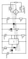
I am a newbie to electronics but I can read schematics and do soldering good. I have once searched and found the attached diagram on a blog. I got ALL exact components and connected but it didn't work. I even did twice, still didn't work.

Recently, I have been thinking, I have the 12v buzzer and a 12V adapter which I can just hook up directly to the utility mains and the alarm goes off but how to make the buzzer go for a few seconds and stop is what I can't calculate on my own.

Can anyone give a circuit which I can add between the adapter and buzzer to control the duration of the buzzer and also get it set for the next operation cycle.

Thanks.
 

Attachments

bertus

Joined Apr 5, 2008
22,270
Hello,

The shown circuit is not allowed on this forum.
It is a direct mains powered circuit without a transformer.
For safety you could use a 12 volts transformer.

buzzer circuit isolated.jpg

Bertus
 

crutschow

Joined Mar 14, 2008
34,283
For safety you could use a 12 volts transformer.
He stated he had a 12V adapter.

That circuit has an apparent error.
The rectified voltage is connected directly to the 555 output through the right-hand diode, so I don't see how 555 can shut the buzzer off, and will likely get zapped in trying.
That's likely why it didn't work for the TS.

Below is a simplification of the 555 circuit that should do what you want.
Vs is the 12Vdc power from your adapter.

Upon power application TRIG is low, which triggers the 555 output high.
When C1 (red trace) charges to the THRS trigger level (about 2/3 Vcc), the output is reset to low.
Since the capacitor DIScharge pin is not connected, the capacitor stays charged, and the 555 stays in the reset state as long as the power is applied.

The pulse time is about 1.1 times the R2C1 time-constant (giving 5 seconds in the LTspice simulation, blue trace).

If the buzzer takes more than about 100mA, you will need to add a transistor buffer on the output.

upload_2019-5-21_13-50-3.png
 
Last edited:

Thread Starter

Khaleef

Joined Mar 22, 2017
105
He stated he had a 12V adapter.

That circuit has an apparent error.
The rectified voltage is connected directly to the 555 output through the right-hand diode, so I don't see how 555 can shut the buzzer off, and will likely get zapped in trying.
That's likely why it didn't work for the TS.

Below is a simplification of the 555 circuit that should do what you want.
Vs is the 12Vdc power from your adapter.

Upon power application TRIG is low, which triggers the 555 output high.
When C1 (red trace) charges to the THRS trigger level (about 2/3 Vcc), the output is reset to low.
Since the capacitor DIScharge pin is not connected, the capacitor stays charged, and the 555 stays in the reset state as long as the power is applied.

The pulse time is about 1.1 times the R2C1 time-constant (giving 5 seconds in the LTspice simulation, blue trace).

If the buzzer takes more than about 100mA, you will need to add a transistor buffer on the output.

View attachment 177913
Thank you Crutschow. I'm sorry but looking at the schematic, do I still make use of the 12v adapter? Where do they connect in the diagram, didn't get that. Thanks.

***Edit***
I think I get it. The arrows point downwards are GND (Ground/Negative)

Am I right?
 
Last edited:

Zaishens

Joined May 20, 2019
28
Hello @crutschow, how many volts is the 10uf Capacitor? Also, what determines the duration of the buzzer?
As seen in his simulation the capacitor charges up to about 9V, but since it's a 12V circuit, I would pick a capacitor that is rated for atleast 12V, more is better.

The duration is like he said: "The pulse time is about 1.1 times the R2C1 time-constant"
So 450kohm x 10uF x 1.1 = 4.95s. as seen in the simulation, this is not so precise, but good enough for your application.
 

Thread Starter

Khaleef

Joined Mar 22, 2017
105
As seen in his simulation the capacitor charges up to about 9V, but since it's a 12V circuit, I would pick a capacitor that is rated for atleast 12V, more is better.

The duration is like he said: "The pulse time is about 1.1 times the R2C1 time-constant"
So 450kohm x 10uF x 1.1 = 4.95s. as seen in the simulation, this is not so precise, but good enough for your application.
Thanks @Zaishens, so I could pick 12v and above capacitor and I'll be fine?
 

Zaishens

Joined May 20, 2019
28
Thanks @Zaishens, so I could pick 12v and above capacitor and I'll be fine?
Yea, 16V is standard...

BTW, im surprised that the cap only charges to 9V, I think this is wrong somehow. According to me, it will charge all the way to 12V, but that's no problem when you use 16V cap.
 
Last edited:

Tonyr1084

Joined Sep 24, 2015
7,853
Here's a blackout buzzer. It consists of a 12 volt transformer (working with mains is a disallowed topic), a SPDT relay (12 volt rated), an automobile blinker module, a light bulb, a buzzer and a cancel switch. [edit] Blinker module needs to be the thermal type - not the electronic version. {end edit}

Assume power has been off and the relay has fallen to the NC position. When power comes on the 12 volts will pass through the relay, the blinker, the bulb and the buzzer. When it comes to your attention you simply press the switch to cancel the buzzer and activate the relay. Once the relay is activated it will keep itself turned on until the next power failure.

While power is still on you can test the blinker / buzzer any time you like. Simply press the momentary switch and the blinker, buzzer and bulb will be in circuit and you can make sure the system is working.

Blackout Buzzer.png
 

Thread Starter

Khaleef

Joined Mar 22, 2017
105
Here's a blackout buzzer. It consists of a 12 volt transformer (working with mains is a disallowed topic), a SPDT relay (12 volt rated), an automobile blinker module, a light bulb, a buzzer and a cancel switch. [edit] Blinker module needs to be the thermal type - not the electronic version. {end edit}

Assume power has been off and the relay has fallen to the NC position. When power comes on the 12 volts will pass through the relay, the blinker, the bulb and the buzzer. When it comes to your attention you simply press the switch to cancel the buzzer and activate the relay. Once the relay is activated it will keep itself turned on until the next power failure.

While power is still on you can test the blinker / buzzer any time you like. Simply press the momentary switch and the blinker, buzzer and bulb will be in circuit and you can make sure the system is working.

View attachment 178065
Thanks @Tonyr1084 If Cruts circuit works (I haven't tried), it's more simpler, no switches, no relays. Do I still need a 12v transformer ?cos I have a 12v adapter already which if I connect to the buzzer, would beep. I just need a circuit in between the adapter and the buzzer that would manage how long the buzzer beeps.
 

crutschow

Joined Mar 14, 2008
34,283
BTW, im surprised that the cap only charges to 9V,
I thought so also, so I checked.
On the simulation I measured current flow into the THRS input (green trace below) when the voltage goes about 1V above it's threshold voltage (about 2/3 Vss), which clamps the cap voltage at that value.

upload_2019-5-23_11-25-48.png

Looking at the 555 schematic (below) it would seen that Q1 starts to conduct base-emitter current when it's voltage is about two base-emitter drops (from Q1 and Q1) about the threshold voltage (CONTROL VOLTAGE) at which point the transistors are saturated.

But a test with a real 555 is needed to confirm this.

upload_2019-5-23_11-17-7.png
 

Tonyr1084

Joined Sep 24, 2015
7,853
Do I still need a 12v transformer?
No. Not if you have a reliable 12 volt supply. My drawing included it because I wanted to be sure we weren't discussing mains voltages.

As for your alert - - - If you're not home, power goes out, power comes back before you're home to hear the alert and it times out - how do you know you had a power failure? Is that important to you? My drawing requires you interact with it. If you're sleeping and power goes out then comes back, if you sleep through the beeping you might not know your alarm clock may possibly be off. My circuit will annoy you to the point of getting up and checking things. If something needs attention - you're up.

I'm sure you know better what it is you want to do. I just thought this circuit would be quick and easy. No timers, no RC circuits, and probably less fun to build. But I've always liked getting things done the most expedient way. Whatever you choose - choose because you believe it serves your purpose best.

Good luck.
 

MisterBill2

Joined Jan 23, 2018
18,176
The very simplest "buzzer" alerting arrangement for knowing when the mains power returns, given that there is a reliable 12 volt DC power supply connected that will provide the 12 volts when the power comes back on, is simple. Have a DC powered Sonalert device, or equivalent, since lots of companies make them now, and an electrolytic capacitor rated at least 16 volts, in series, with the capacitor + connected to the source, and the capacitor - connected to the sounder +, with the sounder negative terminal connected to the supply negative terminal. When the supply voltage returns the sonalert will sound and eventually fade out as the capacitor charges. Depending on the capacitance and the current drawn the time can vary from a few seconds to several minutes, the greater the capacitance the longer the sound. This method will also work with a mechanical buzzer or bell. It is about as simple as it can get.
 

Tonyr1084

Joined Sep 24, 2015
7,853
@MisterBill2: When power goes out for a few seconds, how does the cap discharge? How long would the power have to be out for the cap to discharge sufficiently so that when power is restored the sonalert will ring again for the desired duration?
 

Thread Starter

Khaleef

Joined Mar 22, 2017
105
The very simplest "buzzer" alerting arrangement for knowing when the mains power returns, given that there is a reliable 12 volt DC power supply connected that will provide the 12 volts when the power comes back on, is simple. Have a DC powered Sonalert device, or equivalent, since lots of companies make them now, and an electrolytic capacitor rated at least 16 volts, in series, with the capacitor + connected to the source, and the capacitor - connected to the sounder +, with the sounder negative terminal connected to the supply negative terminal. When the supply voltage returns the sonalert will sound and eventually fade out as the capacitor charges. Depending on the capacitance and the current drawn the time can vary from a few seconds to several minutes, the greater the capacitance the longer the sound. This method will also work with a mechanical buzzer or bell. It is about as simple as it can get.
Nice, your circuit doesn't require the 555 component?
 

Tonyr1084

Joined Sep 24, 2015
7,853
@MisterBill2 MisterBill2's design (resistor added to bleed cap when power is out) There will have to be a bleeder resistor of large enough value so as to not drive the sonalert but not so high that it doesn't discharge the capacitor quickly enough during power failure.

Blackout Alert.png
 

crutschow

Joined Mar 14, 2008
34,283
Here's a schematic of the Sonalert circuit.
It adds a diode and bleeder resistor, such that the bleeder resistor current does not go through the Sonalert after the capacitor is charged, to avoid the problem Tony mentioned.
The value for the capacitor and bleeder resistor may need to be adjusted, depending upon how much current the Sonalert you select requires, and how fast you want it to recover after the power goes out.

upload_2019-5-23_19-29-16.png
 
Last edited:
Top