I made my first amplifier!

Thread Starter

babaliaris

Joined Nov 19, 2019
160

IMG_20201021_215428.jpg

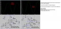
We kinda learned about this circuit in the electronics 1 lab, but I don't understand everything, i have some questions and unfortunatly my lab professor is quite a Karen and won't even hear my questions... Anyway, these are my questions:

1) Which elements can I mess with to increase the volume of the amplifier? The only thing I can think of is R1and R2 (decrease them for example) so that ib will become bigger => Ic = b * Ib will also become bigger in amplitude so more volume!!! (But I need to be careful not to burn the transistor).

2) Capacitors C1, C2 do they help in the amplitude amplification? If I change their capacitance will it make a difference?

3) If I don't use the C1 capacitor, and short the input signal (In) with the R1, R2 voltage divider (B node) then I don't hear anything!!! Why do I need this capacitor? I heard that it acts as a filter, but I don't know about filters yet (actually I skipped them in the theory.:p

4) Do I need R3 which is parallel with C2 or can I just put C2 directly in series with the emitter and the ground?

5) How does C2 fixes the distortion of the output signal?

Thank you for your time.
 
Last edited by a moderator:

ZCochran98

Joined Jul 24, 2018
303
One suggestion: move your connection point "A" to above the speaker - that may help with operation a little.

Now, to (attempt to) answer your questions:
1) You can try adjusting the resistors - namely, reducing R3. However, you don't want to reduce it too much, or you may end up dissipating too much power in it (which will possibly burn it). Current is controlled more by the base input current, so try reducing R3 a little and see what happens.

2) C1 and C2 do not help with amplification, in one sense. What they do is act as a way to allow for AC signals. Changing their capacitance will change your low-frequency cutoff point (so increase the capacitors to reduce the low-frequency cutoff point). To be specific, C1 acts as a way to isolate DC signals from your AC signal, and C2 acts as a short for AC signals, allowing AC (but not DC) signals to (mostly) bypass R3, which makes calculations easier (as, from an AC point-of-view, the emitter is then shorted to the ground, which improves stability somewhat).

3) The reason that if you don't have a C1 capacitor you don't have any input is because of several things. Having C1 there limits the paths that DC current can take - into R2 and into the transistor base - you will have no DC current flowing into your signal source. It acts as a "filter" for DC signals - none may pass.

4) R3 needs to be in parallel with C2. Otherwise, if they're in series, the voltage across C2 (or C2 with respect to the ground, depending on where you connect it) will be your voltage source level, as capacitors act as open circuits to DC signals. What will happen then is that the DC operating point of the amplifier, which sets all the actual gain properties of the system, will no longer be set, and you will have no overall current flow. Or, at least, nothing useful.

5) C2 fixes distortion because, without it, your emitter (in the AC analysis) will no longer be shorted, making calculation of gain a little more challenging. Instead, you'll end up with both your DC and AC signals across that resistor as well (not just a DC voltage drop). Depending on the size of that resistor, it may also cause an unstable operating point of the transistor, so it may continuously change the overall gain. It may also help to reduce noise, but I'm not sure (I'd have to do the calculation to check).

Hope these answer your questions! And remember: when in doubt, you have the circuit - physically try a couple of these questions and see what happens.
 

Thread Starter

babaliaris

Joined Nov 19, 2019
160
One suggestion: move your connection point "A" to above the speaker - that may help with operation a little.

Now, to (attempt to) answer your questions:
1) You can try adjusting the resistors - namely, reducing R3. However, you don't want to reduce it too much, or you may end up dissipating too much power in it (which will possibly burn it). Current is controlled more by the base input current, so try reducing R3 a little and see what happens.

2) C1 and C2 do not help with amplification, in one sense. What they do is act as a way to allow for AC signals. Changing their capacitance will change your low-frequency cutoff point (so increase the capacitors to reduce the low-frequency cutoff point). To be specific, C1 acts as a way to isolate DC signals from your AC signal, and C2 acts as a short for AC signals, allowing AC (but not DC) signals to (mostly) bypass R3, which makes calculations easier (as, from an AC point-of-view, the emitter is then shorted to the ground, which improves stability somewhat).

3) The reason that if you don't have a C1 capacitor you don't have any input is because of several things. Having C1 there limits the paths that DC current can take - into R2 and into the transistor base - you will have no DC current flowing into your signal source. It acts as a "filter" for DC signals - none may pass.

4) R3 needs to be in parallel with C2. Otherwise, if they're in series, the voltage across C2 (or C2 with respect to the ground, depending on where you connect it) will be your voltage source level, as capacitors act as open circuits to DC signals. What will happen then is that the DC operating point of the amplifier, which sets all the actual gain properties of the system, will no longer be set, and you will have no overall current flow. Or, at least, nothing useful.

5) C2 fixes distortion because, without it, your emitter (in the AC analysis) will no longer be shorted, making calculation of gain a little more challenging. Instead, you'll end up with both your DC and AC signals across that resistor as well (not just a DC voltage drop). Depending on the size of that resistor, it may also cause an unstable operating point of the transistor, so it may continuously change the overall gain. It may also help to reduce noise, but I'm not sure (I'd have to do the calculation to check).

Hope these answer your questions! And remember: when in doubt, you have the circuit - physically try a couple of these questions and see what happens.
Your answers where amazing! It seems I lack a lot of theory too. I will actually save your answers to my notes in order to understand the theory.

One more question: Right now in my university I'm enrolled in 2 subjects:
1) Electrical circuits 2
2) Electronics 1.

In the first the contents are: Loosely coupled circuits, transformers, power (the complex one) and some more stuff... I believe the last chapter is called 4 poll circuits or something like that or maybe 4 pin circuits I'm not sure.

In electronics 1 we currently learn about the diaode and MOSFET transistors. I'm not sure what else we will learn.

Does some of the theory that I'm missing is in those two subject?
 

ZCochran98

Joined Jul 24, 2018
303
It seems you may be missing a little linear circuit analysis, by my guess - specifically, AC/DC analysis of circuitry with capacitors (perhaps reactive impedance? Basically how capacitors act as complex resistors to AC but as open circuits to DC - that kind of thing. You may want to read about low or high pass filters and their theory). Based on what classes you're taking now, I'd assume it was possibly stuff in a prior class. It may be stuff you do already know, but the pieces haven't "come together" quite yet. So, I'd just recommend going back and reviewing a bit of some linear circuit theory. When it comes to these amplifiers, though, thing's aren't always transparent, so even if you are pretty solid with theory, these amplifiers can be kinda challenging. For instance, why C1 and C2 are there isn't initially obvious, especially to students seeing it for the first time.

While some things are possibly in previous classes, you may learn some things in your current classes that will make figuring this stuff out easier. For instance, I suspect the last chapter whose name you were trying to remember is something like "4 port" or "2 port" circuits, which make some of the math or design for these things a little easier.

Personally, I always found the MOSFET circuits easier to analyze than BJT, even though they're largely the same general design (the mathematical setup is easier, as MOSFETs don't have a gate current!).

Good luck with your studies!
 

Audioguru again

Joined Oct 21, 2019
6,673
Your video sounds squeaky and tinny because the speaker is small and does not have an enclosure.
A cheap small speaker cannot produce low frequencies.
Low frequency sounds from the rear of the speaker cancel sounds from the front without an enclosure.

The speaker sounds distorted because your circuit puts DC current in the speaker that pulls its cone fully in or fully out. An audio amplifier output is only AC with no DC current. Then the audio signal swings the cone in and out.

Your amplifier is also distorted because the transistor does not have enough base current and because its power supply voltage of only 5.25V is very low.

I simulated it. Its audio output power is almost nothing at 0.004W but the heating in the speaker is 250 times more at 1W.
 

Attachments

Thread Starter

babaliaris

Joined Nov 19, 2019
160
It seems you may be missing a little linear circuit analysis, by my guess - specifically, AC/DC analysis of circuitry with capacitors (perhaps reactive impedance? Basically how capacitors act as complex resistors to AC but as open circuits to DC - that kind of thing. You may want to read about low or high pass filters and their theory).
Yes, you are right! I know how capacitors and inductors behave in dc but not in ac, although I know how to do calculations in AC with phasors... And also I know nothing about filters (and we use them a lot now in a subject with the name telecommunications 1. I must learn them quickly or I will not be able to follow along.)!
Right now I'm doing a review of all the theory (I just finished Thevenin and Norton equivalents and I'm entering capacitors, inductors, and step response on DC).
 

sparky 1

Joined Nov 3, 2018
756
If you print out Audio Guru's simulation and have a curve trace graph for the transistors operating points (or region).
A small signal will be amplified can be logical as shown on the curve trace graph. note what you have on the board on the print out.
You found the operating point or it was just given and it worked. Some use 'analog discovery' / curve trace in lab. youtube.

The diode and the mosfet are semiconductors. The lab looks at characteristics of BJT transistor operating in a certain region. region not switch mode.
The slight distortion shown in simulation means it is slightly out of that region. but it doesn't have to be perfect. The audio can be digitized.
Since telecom wireless has audio signal type usually modulated digitally the analog form of audio helps make the learning transition progressive into digital modulation. Sometimes we step back and look at the amplifier as a gain block and other times look closely at setting the operating mode of an active semiconductor. There will be other labs that better illustrate gain and filters and so on.
 
Last edited:

Audioguru again

Joined Oct 21, 2019
6,673
I fixed the amplifier by adding a few things but it would produce much more power if its supply voltage is higher and/or if its speaker impedance is lower at 8 ohms or 4 ohms (then output transistors will get hot and should be replaced with transistors that have a metal tab connected to a heatsink).
 

Attachments

Top