Theoretically, the voltage drop in a silicon diode is approximately 0.7V.
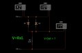
In this particular case (for the attached image) only current flowing through the diode located on the right (D1)--Sorry Say LEFT--
We are applying to the circuit: +15 V and +10 V. therefore the circuit image, just feel +5 V.
Remember: V / I = R, or V / R = I, or RXI = V
Then: 5 - 0.7 = 4.3V which is approx. What it is showing the XMM1 voltmeter.
The voltage drop across D1 is displayed on the voltmeter XMM2 which is very approximate 700mV.
The current flowing through the circuit D1, R1 is indicating on the XMM3 meter which is 1.97mAmp.
4.3/2200 = 0.001954Amp. = 1.1954mAmp.
Through the diode D2 is no current because it is reverse biased.
But ... if we apply alternating current to that circuit then the results will be different from what we've been seeing.
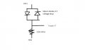
Hi. I'm not sure if I'm seeing a different image than the previous poster, but for me the diode on the left is forward biased, means conducting. Also I only see "V out", not saying what it is referenced to. If it's the voltage drop over the resistor, I agree that it is about 4,3V.
The current will flow through the path where the voltage difference exists , so it will activate one of the diodes and the opening voltage of the diode is aproximately 0.7 volt , so the voltage across the resistor is 5-0.7= 4.3 v
About the other diode , there will be reverse biase current across it but you can ignore it since it is at the values of picoamps

 Facebook
 Google
 GitHub
 Linkedin
 16.2 KB Views: 74