 Facebook
 Google
 GitHub
 Linkedin
Hello,
I need help as on the attached pdf drawing or eagle schematic, i am getting 4.5 volts at ESP and RFID reader.
How it works:
At the input it is 12 VDC, going through 5v dc regulator.
The 5 vdc goes to Lipo charger and also to T1.
T1 it is a switch between 12vdc in and battery.
Then, power goes to an Adafruit minibooster.
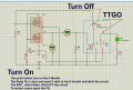
The 5 vdc from booster goes through a Start/Stop circuit.
I use it to save battery power.
When you press the Push button, 5 volts goes to ESP , 5 volts power pin.
When ESP32 get power, put Control line High, and this one latch the ON state.
After i finished the work with ESP, i just turn LOW the control line and power it is shut down from battery/or 12vdc.
The 5 volts goes to the RDM6300 power pin.
Even though it is just a small current on RDM or ESP, the voltage after switch is just 4.5 volts and the card reader cannot work.
Can anybody tell me what i am doing wrong ?
Thank you
I need help as on the attached pdf drawing or eagle schematic, i am getting 4.5 volts at ESP and RFID reader.
How it works:
At the input it is 12 VDC, going through 5v dc regulator.
The 5 vdc goes to Lipo charger and also to T1.
T1 it is a switch between 12vdc in and battery.
Then, power goes to an Adafruit minibooster.
The 5 vdc from booster goes through a Start/Stop circuit.
I use it to save battery power.
When you press the Push button, 5 volts goes to ESP , 5 volts power pin.
When ESP32 get power, put Control line High, and this one latch the ON state.
After i finished the work with ESP, i just turn LOW the control line and power it is shut down from battery/or 12vdc.
The 5 volts goes to the RDM6300 power pin.
Even though it is just a small current on RDM or ESP, the voltage after switch is just 4.5 volts and the card reader cannot work.
Can anybody tell me what i am doing wrong ?
Thank you
Attachments
-
26.7 KB Views: 28
-
54.4 KB Views: 6


")


