Facebook
 Google
 GitHub
 Linkedin
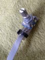
I have this incremental encoder (picture is attached, i think it is EC11) and i want to use it with a PIC16F887 microcontroller.
The encoder has 5 labelled wires (VCC, B, A, BUTTON, GND) and i dont use the buttton.I plugged the 'A' to the PIC's RB3 pin and the 'B' to the PIC's RB4 pin (set up as input pins) and I plugged the 'Vcc' to an arduino uno's 5v and the Ground to the arduino uno's Ground.
In Debugging Mode the PIC can notice the change in the used input pins properly if i rotate the encoder, but the program itself doesn't work properly (Interrupt-On-Change is set up to the encoder's pins, and the program doesnt step in to the Interrupt if i rotate the encoder).
I know my problem is starting to seem like a programming problem and not a wiring one, but i have a strong suspicion that i missed something in the wiring (or done something wrong).
The encoder has 5 labelled wires (VCC, B, A, BUTTON, GND) and i dont use the buttton.I plugged the 'A' to the PIC's RB3 pin and the 'B' to the PIC's RB4 pin (set up as input pins) and I plugged the 'Vcc' to an arduino uno's 5v and the Ground to the arduino uno's Ground.
In Debugging Mode the PIC can notice the change in the used input pins properly if i rotate the encoder, but the program itself doesn't work properly (Interrupt-On-Change is set up to the encoder's pins, and the program doesnt step in to the Interrupt if i rotate the encoder).
I know my problem is starting to seem like a programming problem and not a wiring one, but i have a strong suspicion that i missed something in the wiring (or done something wrong).
Attachments
-
 171.6 KB Views: 18