Facebook
 Google
 GitHub
 Linkedin

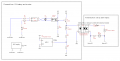
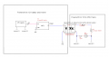
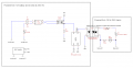
Thanks for your response. Note that I've turned everything the other way around. With the revised circuit, everything - except the heater circuit - comes from the inverter AC (and including +5V supply) so the 130V can only occur on the SSR output side. The other thing is that I need to combine the PWM signal from the MCU with the output from Opt1; if I can conserve Q1 then I can also keep the current on R1 and R2 down at the same time which is better for me, and kill two birds with the same stone. Besides getting very hot and needing new resistors, all that power on R1 and R2 also has to come from the battery. Would that work using Q1?
How to use a signal from mains to control a DC relay?
- Thread starter Bhante
- Start date