You could be right. Some of the TS's posts do seem to suggest that but I was working from his description in post #7. This is one of those posts where working out what the question is is the difficult part.
Yes, this is the configuration I was talking about.
If so the base emitter junction is never reverse biased. If you are using a normal transistor (Not a darlington.) then you would choose R1 to give a base current about one tenth of the load current. R2 is not really required it just reduces any leakage current. I would choose about 10 times the value of R1. It was more important in the days of germanium transistors as they had higher leakage currents than silicon transistors.
The MJ11015 transistor I mentioned is a Darlington PNP with an Ic/Ib of 100. It wasn't the base current, nor resistor which I was wondering about, it was how to ensure that there wasn't 12 volts across the emitter/base junction, when the datasheet states a maximum of 5 volts?
The BE reverse voltage is often as low as 5V, and its usually best avoided. The BE forward volt drop is around 0.7V for a silicon type. The old germainium types were almost immune to the reverse VE vulnerability, but many reasons for not using them - including rare and expensive.
Hard to work out what you're trying to do - but you might fond a P-channel MOSFET less constraining.
The MJ11015 transistor I mentioned is a Darlington PNP with an Ic/Ib of 100. It wasn't the base current, nor resistor which I was wondering about, it was how to ensure that there wasn't 12 volts across the emitter/base junction, when the datasheet states a maximum of 5 volts?
For a 3A fan? You need about 30mA of base current. I'm a little confused what the voltage applied to the base will be. Whatever that is, use Ohm's law ∆V = I • R. In your scenario, ∆V = emitter-base and we already know we want the current I to be 0.03A. Just solve for R. You can probably get away with a bit larger value, no need to go lower.
Apologies for being slow, I misunderstood that you were talking about the resistor value.
I thought there was some new, funky type of resistor that automatically only allowed 1% of the load value to pass. Totally missed the transistor gain of 100. Doh!
When the PNP is a Darlington pair then the Zener diode should be change from 6.2V to 5.6V and you should in series with the PNP as below:
Vin E(P) → C(P) Vout (Darlington pair)
Vin B(N) → (-)5.6V Zd(+) → C(P) Vout
Vb = 0.7V
Vout = 12V - (0.7V+0.7V+5.6V) = 12V - 7V = 5.0V
You need to connected a 200Ω (false load) resistor from Vout to ground when you measure the Vout voltage, the output voltage of this kind of simple PNP circuit will be have a little changing when the draw current of load is changing.
The 200 (false load) resistor is used to provides a 5mA Minimux current for the Zener diode when you to do the test.
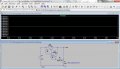
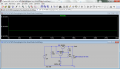
The below is the simulation and the original is used 5.6V zener diode, but I can't find it in the libraries, so I used 6.2V to replace it, something in the simulation can't be the same with the real world, when the Load is drawing more current then the output voltage will be a little different, W = 7V*3A = 21W and it was waste on the darlington pair for nothing.
Thanks for the more detailed explanation. I wasn't completely sure what you had meant before. Unfortunately I don't have a program to open your attachment.
I'll set up a test circuit when I get a minute in a while.
It would be nice to have some voltage regulation seeing how a 12 volt battery is rarely actually 12 volts.

 Facebook
 Google
 GitHub
 Linkedin