How to trim offset of instrumentation amplifier to 0V automatically

Thread Starter

fieryfire

Joined Feb 14, 2017
150
Very interesting idea! you are really slammin' and jammin' now. Some thoughts:

1. If the temperature response of all sensors is predictable, then I think a compensation scheme would work. If they are all the same, then one compensating signal would do it. However, I am thinking there is a temperature gradient through your sensor assembly and they may be a bit different? Perhaps more than one compensating signal is required? Anyway, characterizing the temperature behavior may be a project on it's own.

2. A caution about the DAC output(s). DACs usually have a high output noise level. You will probably need a low pass filter between the DAC and the REF inputs. The REF signal is a sensitive input since there is a gain of only 100 for the signal before it adds to the REF signal. Then, there is a gain of 20 for both. So, any noise on the REF input may be significant.

3. The input impedance of 72 REF inputs in parallel is less than 100 ohms. So you will need to divide them into groups and drive each group with an independent buffer. Or the REF signal source will be overloaded.
:D Thank you so much for the response.

1) The temperature behaviour of all the sensors are not indeed the same, but very identical. Moreover, the initial baseline of all the sensors are quite different. and you are right, there is indeed a temperature gradient. One such fix would be that, i could try to have each channel with a DAC to its REF pin, i first get the baseline via the ADC, and then push a negative value of that back to the DAC to the REF pin, ofcourse this is to be done during a stable state where no measurement is taking place.

2) Agreed in my application the out put noise is expected to be very low, but i get most of the interference from the 50Hz noise, which i cannot filter out as my signal of interest also has 50Hz components from time to time. So yes the output of the DAC with a 0.1Hz cut-off would make sense here. Thanks for the advice

3) I still did not understand about the 76 input impedance calculated to 100Ohm. I am missing this key knowledge here. Could you please explain me more?
 

Thread Starter

fieryfire

Joined Feb 14, 2017
150
Are you using LTspice yet to model your board?
I am trying to model it with LTSpice, but im not sure if i got the modelling correct or not. Especially, the noisy nature of voltage sources were not very well modelled into it.
 

Attachments

Analog Ground

Joined Apr 24, 2019
460
:D Thank you so much for the response.

1) The temperature behaviour of all the sensors are not indeed the same, but very identical. Moreover, the initial baseline of all the sensors are quite different. and you are right, there is indeed a temperature gradient. One such fix would be that, i could try to have each channel with a DAC to its REF pin, i first get the baseline via the ADC, and then push a negative value of that back to the DAC to the REF pin, ofcourse this is to be done during a stable state where no measurement is taking place.

2) Agreed in my application the out put noise is expected to be very low, but i get most of the interference from the 50Hz noise, which i cannot filter out as my signal of interest also has 50Hz components from time to time. So yes the output of the DAC with a 0.1Hz cut-off would make sense here. Thanks for the advice

3) I still did not understand about the 76 input impedance calculated to 100Ohm. I am missing this key knowledge here. Could you please explain me more?
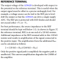
About #3. I was incorrect. The input impedance of the REF input is 120K ohms. So, if driving 76 of them in parallel is 120K/76 or 1.58K ohms.
 

Analog Ground

Joined Apr 24, 2019
460
I am trying to model it with LTSpice, but im not sure if i got the modelling correct or not. Especially, the noisy nature of voltage sources were not very well modelled into it.
The noise from the resistors and the amplifiers is built into the noise analysis. Pickup noise like your 50 Hz and other noise sources must be added. I see you are using the white( ) function. Other sources are covered here:

https://www.allaboutcircuits.com/te...-transient-analysis-noise-simulation-LTspice/
 

Thread Starter

fieryfire

Joined Feb 14, 2017
150
About #3. I was incorrect. The input impedance of the REF input is 120K ohms. So, if driving 76 of them in parallel is 120K/76 or 1.58K ohms.
Hello Again,

Analog Ground. I suppose to have the best performance, i would need to make this reference resistanc as low as possible(well below 1Ohm) But if i connect them all together in parallel to a DAC then i would have Rref=1.58KOhm? which means that i will have a small amplification factor which according to the following formula will give me 1.006536 times? Could you confirm, if i am able to drive with 0 to 5V DAC of the Labjack T7. It says the DAC can generate about 20mA of current. Would this be sufficient to drive the reference voltage of 76 AD8428 instrumentation amplifier. Sorry for ignorance on the subject

upload_2019-7-22_11-28-42.png
 
Top