How to set pot values on a 9V battery charger circuit

Thread Starter

Mike_Nelsen

Joined Jan 15, 2018
13
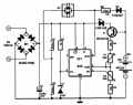
I googled a diagram for building a 9V battery charger using a 555 timer. Turns out I already have all the components necessary to make it. However, the diagram isn't clear on how to set the potentiometer values. Here is a copypaste of the directions I have.

"With the values presented in the circuit diagram, the battery charger NiCd circuit is suitable for 6V and 9V batteries. 9 volt types with 6 and 7 cells are charging with 20mA; P1 must be adjusted so that the NiCd charger disconnects after 14 hours. Window inferior level is set at 1V below this value with P2."

I don't know how to interpret that. Thanks to anyone who can educate me a little. Also here's the associated diagram.
 

Attachments

crutschow

Joined Mar 14, 2008
38,578
Without knowing the purpose of the 555 timer in the circuit, it's difficult to know what the pots are for.
Where did you get that odd circuit?
Was there no write-up about it?
 

MisterBill2

Joined Jan 23, 2018
27,744
The circuit does not seem to actually control the charging of the battery, but it may provide some sort of indication as to what is going on. I would not use this circuit for charging a battery, or for anything else! A legitimate battery charging system needs to both control the applied voltage and also limit the current to avoid damaging the battery. There are a lot of good battery charger circuits around, this is not one of them.
 

ebp

Joined Feb 8, 2018
2,332
The circuit is fairly simple and actually provides charge current from the 555 output with just a resistor for current limiting. The 555 is essentially used as a window comparator. When a discharged battery is inserted the 555 triggers and when it reaches some voltage the 555 turns off.

The current limiting is crude but the magnitude is low. NiCd cells can withstand continuous trickle charging without damage, so ending very low current charging is somewhat pointless. The charger is unsuitable for other types of battery.
 

Thread Starter

Mike_Nelsen

Joined Jan 15, 2018
13
I'd never heard of a window comparator so I looked it up. I think I get it. You're saying it's clocking quick spurts of power to slowly charge the battery and checking if the difference between the battery and charger fits into the voltage 'window' so it knows to stop charging the battery? Assuming I'm on the same page, does that mean P1 and P2 determine that window? Also why only NiCd? Also thx for your help.
 

ebp

Joined Feb 8, 2018
2,332
I shouldn't have called the circuit a "window comparator" because it really isn't one. A window comparator will produce one logic state if the input is between two levels and the opposite state if the input is outside of the two levels. For example if the thresholds are 2 volts and 6 volts, any voltage less than 2 volts or greater than 6 volts will produce one logic state and any value from 2 V to 6 V will produce the opposite state.

The 555 behaves differently. If the voltage at the trigger pin is less than nominal trigger voltage the internal flip-flop is set and the output goes high. The output will remain high until the voltage at the threshold pin rises above nominal threshold voltage, resetting the flip-flop. Normally both trigger and threshold should not be asserted at the same time (the result usually is not spec'd in the datasheet and may not be the same for different manufacturers). If the control voltage (CV) pin is open circuit the trigger voltage is 1/3 of the 555's supply voltage and the threshold is 2/3 of the supply voltage. In the circuit in question the CV pin is set at 4.7 V by a zener diode. The 555 datasheet explains what to expect.

When the 555 is triggered, either by there being no battery in place or because the battery voltage is low, the output goes high. Current from the 555 output through R5 and D5 begins to charge the battery. This state continues until the battery voltage gets to the threshold voltage for the 555, causing its output to go low, ending charging. If the charged battery is left in the charger it will eventually discharge enough to trigger the 555 again and start another cycle. There is no timing as such - the 555 acts purely as a voltage detector. This works because the voltage of a NiCd battery when fully charged will be a little bit higher while current is being applied than it is open-circuit. Setting the trigger or start voltage for the charger to a voltage lower than the battery voltage would be if it were open-circuit after being charged prevents the circuit from constantly turning on and off.

Because P1 is used as a rheostat (2 terminal device), the upper (threshold) voltage must be set first. The lower (trigger) voltage can then be set with P2.

T1 is an "emitter follower" or "common collector" amplifier that applies the battery voltage, minus the base-emitter voltage, across the resistor & potentiometer chain. The current comes from the input supply. This means that very little current is taken from the battery so the charger won't quickly discharge a battery left in-circuit. It isn't a precision circuit, but the base-emitter voltage is sufficiently constant to allow acceptable operation. D4 prevents the battery from discharging through the base-collector junction of T1 if the input supply is turned off. D3 is presumably a bi-color LED that will light up one color if the 555 output is high and the other color if it is low.

There is no voltage regulator so the charging current may vary, but by an acceptable amount.

As long as the current used for charging is small, NiCd cells can be left on the charger indefinitely and will not charge to excessive voltage. No other cell type can tolerate this. NiMH cells must have definitive termination of charging which requires charge endpoint detection (you can find info on the web - often the method is to detect a slight drop in voltage that occurs). Lithium cells must have accurately limited voltage, though they can be repeatedly undercharged without issue, and should not be left on the charger for long periods; Li batteries require charge balancing for each cell. Lead-acid batteries, depending on the type, can stand some over-charge, and can be indefinitely "float charged" if the voltage is accurately regulated. All types must have the maximum current limited. Because they can be trickle charged with low current, NiCd are the easiest cells to charge.
 

bertus

Joined Apr 5, 2008
22,956
Hello,

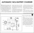
The original circuits is "copied" on the website from a elektor magazine.
Here is a scan from the original elektor dec 1992 article:

Automatic nicad charger elektor dec 92.png

Bertus
 
Top