How to select the right bridge rectifier and relay for this application?

Thread Starter

Xavier Pacheco Paulino

Joined Oct 21, 2015
728
Hello,

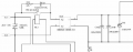
I attach a fragment of circuit found in the internet. I'm trying to design my own circuit similar to that. That design corresponds to a dc motor control board. As you see in the picture, there is the AC input, goes through a relay contact and feed the rectifier. How do I choose my own relay and rectifier? Let's say that the bridge rectifier output goes to the capacitors and feed a 130V, 4HP motor. Do I calculate the max current that my bridge and relay should stand according to the motor ratings, right? If I'm going to feed another part of the circuit with the same DC bus, I need to take into account all of the currents which I expect that will come from out of the bridge.
 

Attachments

MrAl

Joined Jun 17, 2014
11,389
Hello,

This is a little more tricky because the relay is turning on a bank of capacitors and that means a very high current surge when it is turned on if the line voltage phase is not near the zero crossing.
Perhaps something solid state would be better for such a big load, with zero crossing detection for the turn on time.
Relays have to be much over rated for motor loads, something that is often overlooked.
 

dendad

Joined Feb 20, 2016
4,451
One addition you could do is to have 2relays. One switches on feeding the power via a high power resistor to limit the inrush surge, then the second relay shorts out the resistor. Something along those lines was done on the big short wave transmitters I used to work on.
Or as mentiones above, use solid state switching and zero crossing detection to control when power is applied.
Like a high power light dimmer to ramp up the power over a second or two.
Whatever way you go, use a big bribge rectifier as it will need to handle the surge and at least the rated stall current of the motor. In this case, big IS better!
 

Reloadron

Joined Jan 15, 2015
7,501
EDITED:

Never mind as I addressed switching the DC, my bad and thanks Al and dendad for your post which allowed me to instantly see how bad I screwed that up. :)

Ron
 

Thread Starter

Xavier Pacheco Paulino

Joined Oct 21, 2015
728
I really like the idea of using solid state device with zero crossing. However, I don't have much experience designing such kind of circuit. I will look into it. If you have further reference I could read regarding designing that solid state circuit, I would appreciate it.
 

MaxHeadRoom

Joined Jul 18, 2013
28,619
I really like the idea of using solid state device with zero crossing. However, I don't have much experience designing such kind of circuit. I will look into it. If you have further reference I could read regarding designing that solid state circuit, I would appreciate it.
You could use a very small control relay to turn on the Triac (SSD) .
Just Google testing a triac for the simple circuit.
Max.
 

Thread Starter

Xavier Pacheco Paulino

Joined Oct 21, 2015
728
Hello,

This is a little more tricky because the relay is turning on a bank of capacitors and that means a very high current surge when it is turned on if the line voltage phase is not near the zero crossing.
Perhaps something solid state would be better for such a big load, with zero crossing detection for the turn on time.
Relays have to be much over rated for motor loads, something that is often overlooked.
Does zero crossing help minimize effects of inrush current?
 

Thread Starter

Xavier Pacheco Paulino

Joined Oct 21, 2015
728
It would minimize it up to 1/2 cycle, but the inrush will still occur for the duration of ~1 cycle minimum, plus time required to charge smoothing capacitors on the secondary.
Max.
Another question:

Regarding the image in my first post I see two capacitors in parallel of 1500uF/200V. What's the criteria to choose them? Can I use just one capacitor instead of two? How do I calculate the value that I need? I mean, I know the voltage rating should be at least 200V, but how do I choose the capacitance?
 

MaxHeadRoom

Joined Jul 18, 2013
28,619
The capacitance depends on the maximum DC load, and also the higher the value the higher the transformer VA requirement.
How are you controlling the motor? PWM etc?
Is the motor activated immediately at switch on?
Max.
 
Top