How to obtain a linear voltage from grid resistor

ebp

Joined Feb 8, 2018
2,332
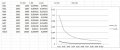
Make the value of R1 very small relative to the value used for R3 to R12. You probably won't like the magnitude of the maximum voltage across R1, but look at the shape of curve. Think about why it is different.

Something else you could try:
Make the value of R2 quite small and operate in bar mode. R2 needs to be low enough in value that when all of the LEDs are on they are all able to operate properly in constant current mode. Disconnect all the other resistors. Plot the voltage across R2 as the input voltage to the 3914 is changed.

Think about what Kirchhoff's voltage law and current law tell you.
 

MisterBill2

Joined Jan 23, 2018
18,502
If you want a voltage that changes as each LED is switched on, use the voltage at the side of R1 that is common to all of the LEDs. It will be 10 volts with all of them off. THEN feed that voltage into the inverting input of an op-amp through a 10K resistor.Also run a 10K resistor to the non-inverting input, fed from the tap on a 10K potentiometer connected between the 10 volt supply and common. Add one more 10K resistor from the output to the inverting input. Now your output voltage will increase as each LED lights, in the bar graph modeBy adjusting the gain and offset you should be able to get the voltage span and magnitude that you seek. But you will need to do some adjusting with the opamp resistor values.
 

MisterBill2

Joined Jan 23, 2018
18,502
For certain those of us in a position to offer useful advice need a lot more understanding about what the desired function is, so that we can offer useful advice. The information given so far does not provide any hint of what sort of control you intend to have.
 

Thread Starter

girafa

Joined Oct 5, 2018
35
I think you very much need to come to an understanding of why what you are attempting has very serious limitations. This is very fundamental stuff.

You set up a spreadsheet to do calculations, but don't seem to understand the result. If you return to your spreadsheet and experiment with reducing the value of R1 you will see that the voltage curve becomes more linear, though with a lower maximum value, as you reduce the value of R1. You need to understand why.
If I reduce the value of R1 the curve keeps because the voltage is always squared.
But if I increase the value of R1 it becomes more linear although with a smaller amplitude.
 

Attachments

Thread Starter

girafa

Joined Oct 5, 2018
35
For certain those of us in a position to offer useful advice need a lot more understanding about what the desired function is, so that we can offer useful advice. The information given so far does not provide any hint of what sort of control you intend to have.
II need to make an analog clock with 60 leds for seconds 60 leds for minutes and 12 leds for hours.

I have the problem to increase the minutes and increase the hours.

I intend to use LM3914 to reduce the number of components.

The trouble always puts in keeping the voltages for the minutes and hours.

Charging a capacitor for the hours is very difficult. A great condenser and a very great resistance is necessary.

The use of the feedback of the voltage of the leds is to have a value by thresholds that will be increased with each impulse


I have to use analog components, otherwise it would be easier.
 

ebp

Joined Feb 8, 2018
2,332
I'm sorry, you are quite right. I was thinking about a different circuit instead of what you were actually using.

If you connect the circuit in the normal way and configure it so the LED current would be 2 mA per LED (lowest available current, according to the datasheet) and operated in bar mode, then as each LED turned on the current from the power supply to the anodes of the LEDs would increase by 2 mA, so you would get 2, 4, 6 ... 20 mA. If opened the connection between the anodes (all connected together) and the power supply and put in a resistor, the voltage across the resistor would be proportional to the current and therefore linear. The performance of the current sources is not perfect but is not too bad - see Electrical Characteristics on page 4 of the TI datasheet.

Instead of using a resistor, you could use a "current mirror" made with two PNP transistors and one (or maybe 3) resistors. Ideally, the transistors should be matched, but if you put a small resistor in the emitter circuit of each, it helps to overcome imperfect matching. Using the mirror means you can get a voltage relative to circuit common (ground). One problem with this idea with this circuit is that it would take 40 mA - 20 mA on the input side of the mirror and 20 mA on the output. I don't know how well a simple mirror circuit would perform at 20 mA.

Without using different resistor values in your original circuit, I can't think of a way to do what you want with this IC.
 
Top