How to obtain a linear voltage from grid resistor

Thread Starter

girafa

Joined Oct 5, 2018
35
Hello
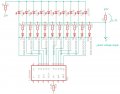
I need to get a linear voltage from the NPN output of the LM3914.

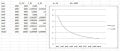
I verify that the output voltage is not linear but exponential.

Note: the resistor that is connected to 0v, instead of is connected to 10v.

The leds is configured in dot mode.


What is the best way to get a linear voltage for the LED that is on? I know that if you use resistors of 1k 2k 4k 8k 16k 32k ... it is possible to keep the voltage linear but since there are many resistors I intend to use equal values.

Thank you
 

Attachments

Thread Starter

girafa

Joined Oct 5, 2018
35
The LM3914 output is a constant current sink to drive the LEDs.
What do you mean "linear output voltage"?
Linear with respect to what?

It's not clear what you are trying to do. o_O

Hi,

linear voltage relative to the LED position.
Can be:
led n1 = 1v
led n2 = 2v
led n3 = 3v
...
...
Or other voltage that is linear.
Because I will have 6 integrated circuits connected in series and need to have the feed-back of the LED that is active.

Thanks
 

Thread Starter

girafa

Joined Oct 5, 2018
35
So what do you actually get?
Actually i get in the "A Linear voltage output point" a voltage value that is not linear. It is exponential because the resistors R3 ... to R12 configuration. The way they are connected will generate a non linear voltage at "A" point. So I need to get a linear voltage value at point "A".

Do you understand?
 

Thread Starter

girafa

Joined Oct 5, 2018
35
The voltage across R2 will have a linear relationship with the number of LEDs which are lit.
No No!!!

Not is linear relationship with the number of LEDs which are lit!

That's my problema!

I need a solution to make the voltage across R2 linear.
 

AlbertHall

Joined Jun 4, 2014
12,343
Anything to do with the LED outputs of the '3914 will always be stepwise related to the input voltage. The input voltage is linear. Why not just use that?
 

Thread Starter

girafa

Joined Oct 5, 2018
35
Anything to do with the LED outputs of the '3914 will always be stepwise related to the input voltage. The input voltage is linear. Why not just use that?
I need to use the "A" or R2 voltage as a feed back to create a analog memory.

Imagine to use each led as hours. Then every hour I add the feed back "A" with a voltage value of 1V, and put on pin 5 of the IC, so the feedback increases a voltage value and waits another hour ....

Is the way I see to increase led by led every hour.
 

AlbertHall

Joined Jun 4, 2014
12,343
You might be better off using a counter, for instance a CD4017 which counts input pulses and sets one of ten outputs high. So you connect your once per hour signal to the input and LEDs on the output will advance one at a time.
Something like this:
 

Thread Starter

girafa

Joined Oct 5, 2018
35
You might be better off using a counter, for instance a CD4017 which counts input pulses and sets one of ten outputs high. So you connect your once per hour signal to the input and LEDs on the output will advance one at a time.
Something like this:
Yes I know, but in this project it is forbidden to use digital circuits. Only analog.

With digital electronics, it was much more easy.

It has to be analog.
 

Thread Starter

girafa

Joined Oct 5, 2018
35
So we're doing your homework are we?
No, no! You're wrong. My question concerns a small part of the project.
I do not want them to do the housework for me! I do not know why you say that!

I simply want to exchange ideas about the details of the project.

Anyway, I appreciate your support.
 

ebp

Joined Feb 8, 2018
2,332
I see no mechanism to get any output voltage other than something very very small and not well defined.

How do you expect any current to flow through R1?
 

Thread Starter

girafa

Joined Oct 5, 2018
35
I see no mechanism to get any output voltage other than something very very small and not well defined.

How do you expect any current to flow through R1?
In another post I explained that R1 was connected to 10V. To avoid confusion I changed the image and put it here.
 

Attachments

ebp

Joined Feb 8, 2018
2,332
OK, at least that will do something. So your expectation is that when a LED turns ON, current will flow through the associated 1N4148, resistor and R1, pulling the voltage of R1 down?

numbered for easy reply:
  1. Are you actually operating in dot mode or bar mode?
  2. Are the resistors really all the same value?
  3. Why is R2 used? (I'm not saying it is wrong, I'm just not clear on your intent.)
  4. Have you measured the voltage between an output that is ON and circuit common (ground)?
 

Thread Starter

girafa

Joined Oct 5, 2018
35
OK, at least that will do something. So your expectation is that when a LED turns ON, current will flow through the associated 1N4148, resistor and R1, pulling the voltage of R1 down?

numbered for easy reply:
  1. Are you actually operating in dot mode or bar mode?
  2. Are the resistors really all the same value?
  3. Why is R2 used? (I'm not saying it is wrong, I'm just not clear on your intent.)
  4. Have you measured the voltage between an output that is ON and circuit common (ground)?
1. Actually operating in dot mode.
2. Yes
3. R2 is used just to limit the current cross the LEDs and put the IC output transistors more satured possible.
4. Yes 0.35v aprox.

The goal is to have a voltage that increases or decreases linearly depending on the led that is connected.
Example:
Led1 V_R1 = 8.5v
Led2 V_R1 = 8.0v
Led3 V_R1 = 7,5v
Led4 V_R1 = 7.0v
...
...
 

ebp

Joined Feb 8, 2018
2,332
R2 does do what I though you probably intended. You don't need it to limit the LED current because the drivers are constant current, but if the resistor value is large enough the CC drivers will turn on more like switches to ground than current sinks.

What I don't understand is how you expect the voltage to change if you are operating in dot mode (one LED on at a time) if all the resistors are the same value. You never have more than one resistor switched into the circuit at a time. In bar mode, each additional LED that was on would add another resistor in parallel, but that won't give linear output voltage with equal value resistors either (I suggest you use a spreadsheet to calculate the expected output voltages). You would get a reasonably linear output current, but to convert that to a voltage requires either an op amp or a current mirror. You could make R2 very small in value, but then the maximum voltage across it will be small (return to the spreadsheet to see how this works).
 
Top