how to move the potentiometer off board?

Thread Starter

LAOADAM

Joined Nov 21, 2018
915
Hi all.
I used a DC DC convert to drive the mcu in my unit of light control as picture, I'd like to move the potentiometer off the board and connected with wires to put on the surface of the unit box, tried two of them all failed to adjust the voltage.
what I can think is my desoldering damaged the pcb copper in that small area? or burn some chip?
any ideas please.

Thanks
Adam

dcdc.JPG
 

Jerry-Hat-Trick

Joined Aug 31, 2022
596
Maybe you could post a photo of the other side showing the detail of your unsoldering? It’s tricky to unsolder three pins in a row. Does the trimmer pot still function as it should and have you tried soldering it back in? Is the resistance value written on it and did you try to replace with the same value?
 

Thread Starter

LAOADAM

Joined Nov 21, 2018
915
Maybe you could post a photo of the other side showing the detail of your unsoldering? It’s tricky to unsolder three pins in a row. Does the trimmer pot still function as it should and have you tried soldering it back in? Is the resistance value written on it and did you try to replace with the same value?
Sure.
dcdc1.JPGdcdc2.JPG

BOX:
photo_2024-05-01_13-04-47.jpg

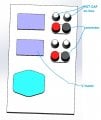
attached the box face, like to get suggestions about the layout.
 
Last edited:

Dodgydave

Joined Jun 22, 2012
11,393
These are multi layer pcbs, very difficult to remove components, probably easier to cut the potentiometer in half, then you can pull the leads out one at a time, and put a new potentiometer off board.
 

Thread Starter

LAOADAM

Joined Nov 21, 2018
915
These are multi layer pcbs, very difficult to remove components, probably easier to cut the potentiometer in half, then you can pull the leads out one at a time, and put a new potentiometer off board.
good. I'll do that way.

Replenish a little about the panel, what I worry for is the connector may affect the pot using? I may put this way, the connector is kind of far from the meter? photo_2024-05-01_15-09-48.jpg
 
Last edited:

MisterBill2

Joined Jan 23, 2018
19,638
What I see is a 10,000 ohm thru-hole pot. I doubt that PCB is more than double-sided. IN addition, it does not look like the pot has been unsoldered from the board. But certainly there are connections on both the top and bottom of the board and so it is likely that the top connections were not adequately connected to the wires that go to the remote potentiometer. That is a common problem if the thru-holes were not plated thru, or if the plating came off when the pot was removed.
 
Top