 Facebook
 Google
 GitHub
 Linkedin
Hello,
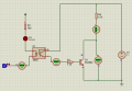
I attach a simple circuit about an opto and a transistor. According to the simulation, base current is 1.92 mA while collector current is 2.53 mA because of the limiting resistor of 4.7k. How can I demonstrate that the base current is 1.92 mA from that circuit?
I attach a simple circuit about an opto and a transistor. According to the simulation, base current is 1.92 mA while collector current is 2.53 mA because of the limiting resistor of 4.7k. How can I demonstrate that the base current is 1.92 mA from that circuit?
Attachments
-
 18.4 KB Views: 21


