 Facebook
 Google
 GitHub
 Linkedin
Hi,
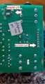
I am building an effects pedal at the minute that requires a mains supply but also has the option to run it on a 9v battery. I've also got a circuit board that I'm trying to reverse engineer to work out how it operates but doesn't make any sense to me as the mains power supply goes into the circuit one way from the positive pin then the battery clip positive goes from the side pin of the barrel jack through the battery then out to the input TRS jack on the Ring that isn't connected to anything else. I'm not sure how the power gets in to the circuit from the battery. Looking at it there's a diode coming out from positive mains via a resistor, the diode in parallel with a capacitor. I didn't know if this had anything to do with it but I just expected this to be to breakdown over 9v and the cap for noise rather than for any sort of current running through the battery from the mains.. Here's a picture of the circuit. It looks very basic but there's something I'm missing...
Many thanks (English-only site -Moderator.)
Attachments
-
 201 KB Views: 15
Last edited by a moderator:


