Facebook
 Google
 GitHub
 Linkedin


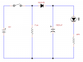
All of the components, including the coin cells, will take up very little area. If you wanted to use surface mount components all of the components, excluding the coin cells, would take up the space of something like a quarter. With through-hole components they should still pretty easily fit in a space that is less than, say, 1.5" on a side.I am in awe! Being a beginner, I never saw such complex circuit diagrams before.
Thank you for the time and effort you spent putting them together. I appreciate that. Like I said earlier, I don't want to take too much of your time, because I don't know if I want to implement this for my hovercraft right now.
I think there are several potential issues with this circuit (please correct me if I'm wrong on any of them):
- It would be difficult to fit all of the components underneath the foam plate, which is about 6in in diameter and ½in deep and has a 2in-diameter hole in the middle for the fan to blow through.
- There is a lot of variability of the duration in which the LED should/would fade out. This would be affected by: (a) strength of 9V battery, (b) strength of coin cells, (c) transistor gain, which you said can vary by a factor of three or four.
- Sorry, but it's far more complicated than what I would want for a small hobby project.
The circuits that use multiple transistors will have very little dependence on the transistor gain. There will be some variation due to the strengths of the batteries, but I doubt it would be that bothersome. The same is going to be true for you original (patched) approach. The time can be made more regular by adding some regulation via zener diodes, and actual voltage regulator (which is the same size as the transistors), or using a 555 timer.
As for the complexity, that is definitely something that you have to decide for yourself.