How to Generate a Tri-level signal.

Thread Starter

lindula

Joined Sep 23, 2016
94

Attachments

MisterBill2

Joined Jan 23, 2018
18,167
I see four distinct voltages, since zero is certainly a voltage. A 2 STAGE binary counter driving a 4:1 multiplexer IC such as a CD4053, with each input set to a specific voltage level. you will need to provide the driving frequency. Or use a 4017 decade counter and a 4051 quad gate and a bit of or gating to get the one wider dwell time.
BUT this is all guessing since we don't have a clue about either the current desired or the time at each voltage level.
 

AnalogKid

Joined Aug 1, 2013
10,986
If it were NTSC, the -300 mV pulse would be horizontal sync, about 4.8 us wide, and the front porch is about 1.5 us. I don't think standard or HC CMOS can handle those speeds, and the signal he is asking about is much faster.

For a 1920 x 1080, 60 Hz, 1:1 signal, the same part of the waveform (B) is (40 or 44) / 148.5x10^6, or 296 ns. Way too fast for CD-series CMOS.

https://www.appliedelectronics.com/documents/Guide to Standard HD Digital Video Measurements.pdf -- pages 19-20

NOTE: The waveform segment called "B" on page 20 is *not* the same as segment B in post #1.

ak
 
Last edited:

jpanhalt

Joined Jan 18, 2008
11,087
I thought "tri-state" meant high, low, and high impedance (undefined or unknown), not high (e.g., +5V) low (e.g., -5V) and neither (e.g., 0V)
 

Papabravo

Joined Feb 24, 2006
21,157
I think two analog switches connecting the higher two levels to a summing junction should do the trick. When both switches are open the lowest level comes through the summing amplifier. When the lower switch is enabled the difference between low an middle is added to the summing junction. When the upper switch is enabled the difference between is added to the summing junction. You should ensure that you don't enable the upper switch with the lower switch open. The voltages applied to the summing junctions should be the differences between the levels.

You can also use a diode combiner. The input voltages can be 0.7 volts higher than required, and you connect the three cathodes together.
 

Thread Starter

lindula

Joined Sep 23, 2016
94
If it were NTSC, the -300 mV pulse would be horizontal sync, about 4.8 us wide, and the front porch is about 1.5 us. I don't think standard or HC CMOS can handle those speeds, and the signal he is asking about is much faster.

For a 1920 x 1080, 60 Hz, 1:1 signal, the same part of the waveform (B) is (40 or 44) / 148.5x10^6, or 296 ns. Way too fast for CD-series CMOS.

https://www.appliedelectronics.com/documents/Guide to Standard HD Digital Video Measurements.pdf -- pages 19-20

NOTE: The waveform segment called "B" on page 20 is *not* the same as segment B in post #1.

ak
Here is the signal I need to generate:
https://en.wikipedia.org/wiki/Tri-level_sync
The main pulse definition is as follows: a negative-going pulse of 300 mV lasting 40 sample clocks followed by a positive-going pulse of 300 mV lasting 40 sample clocks. The allowed rise/fall time for each of the transitions is 4 sample clocks. This is with a clock rate of 74.25 MHz

Thank you for the link I will check that out.
 

Thread Starter

lindula

Joined Sep 23, 2016
94
I forgot to mention my application. I need to generate a tri-level sync input to a SDI camera. I'm looking at digitally controlled analog switches and then connect the outputs together and use a RC-low pass filter. I still trying to find the right device. Maybe the CD4053 would work.
Thank you,
Joe
 

Thread Starter

lindula

Joined Sep 23, 2016
94
I think two analog switches connecting the higher two levels to a summing junction should do the trick. When both switches are open the lowest level comes through the summing amplifier. When the lower switch is enabled the difference between low an middle is added to the summing junction. When the upper switch is enabled the difference between is added to the summing junction. You should ensure that you don't enable the upper switch with the lower switch open. The voltages applied to the summing junctions should be the differences between the levels.

You can also use a diode combiner. The input voltages can be 0.7 volts higher than required, and you connect the three cathodes together.
Thank you very much. I will look into a Diode Combiner circuit.
 

Thread Starter

lindula

Joined Sep 23, 2016
94
I think this project is more complex than you say. Are you making the video also? or are you just adding a new level to video that already exists?
Hello, I'm not making the video signal only making the Gen Lock (Tri-Level) signal that will synchronize the output of the Camera.
 

ronsimpson

Joined Oct 7, 2019
2,985
FPGA to switch between the 0.7V, 0.3V and -0.3V but maybe there is a better way.
Video is often ac coupled. The levels are not really what they look like in a book. The levels vary depending on many things.
"Black Level" does not have to be at 0 volts. Your picture is saying that you have a signal that is below BL by 300mV and a signal that is above BL by 300mV. BL is not known.
1581208013038.png
It is common with video to look for the end of sync and then clamp BL to a reference level. (could be 0V or any voltage)
The point of BL is to have a point in video that is known black. Then to clamp this level to a known voltage at the receiving end. Some video signals have traveled 1000 of miles to get to you and black is lost and must be found at the receiver.
 

Thread Starter

lindula

Joined Sep 23, 2016
94
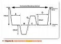
Hello, I'm looking for ideas on how to generate a Tri-level signal such the one I attached to this message. I could use Digitally Controlled Analog Switch that is controlled by an FPGA to switch between the 0.7V, 0.3V and -0.3V but maybe there is a better way.

Here is a switch that might work:

https://www.maximintegrated.com/en/products/analog/analog-switches-multiplexers/MAX4737.html


If anyone has some ideas. Please let me know.

Thank you,
Joe
I've learned that I only need to generate +300mV and -300mV pulses.
 

Thread Starter

lindula

Joined Sep 23, 2016
94
Video is often ac coupled. The levels are not really what they look like in a book. The levels vary depending on many things.
"Black Level" does not have to be at 0 volts. Your picture is saying that you have a signal that is below BL by 300mV and a signal that is above BL by 300mV. BL is not known.
View attachment 198643
It is common with video to look for the end of sync and then clamp BL to a reference level. (could be 0V or any voltage)
The point of BL is to have a point in video that is known black. Then to clamp this level to a known voltage at the receiving end. Some video signals have traveled 1000 of miles to get to you and black is lost and must be found at the receiver.
Sorry for the confusion, I'm only generating the Gen Locking input to a SDI camera. I'm not generating any Video signals, only a synchronization pulses.
 

Thread Starter

lindula

Joined Sep 23, 2016
94
Trouble I'm finding is that my switching speeds need to be about 13nsec if I'm going to support a 3G SDI Tri-Level signals. The clock rate is 148.5Mhz. The Digitally Controlled Analog switches have a Ton,Toff much higher than 13nsec. I can find some with lower Ton and Toff but don't support -300mV inputs. Using a switch would be easy since I am using an FPGA to control the inputs.

Still looking?
 

ronsimpson

Joined Oct 7, 2019
2,985
I'm only generating the Gen Locking input to a SDI camera. I'm not generating any Video signals, only a synchronization pulses.
I am confused. What camera? My cameras have "TTL levels" for gen lock. Not 300mV. Can you find the page in the manual for this?
 

Thread Starter

lindula

Joined Sep 23, 2016
94
I'm looking at the TMUX1109 and it is looking pretty good. This has 2 4:1 multiplexors with a Ton and Toff of 22nsec, 12nsec.
 

Thread Starter

lindula

Joined Sep 23, 2016
94
I am confused. What camera? My cameras have "TTL levels" for gen lock. Not 300mV. Can you find the page in the manual for this?
The main pulse definition is as follows: a negative-going pulse of 300 mV lasting 40 sample clocks followed by a positive-going pulse of 300 mV lasting 40 sample clocks. The allowed rise/fall time for each of the transitions is 4 sample clocks. This is with a clock rate of 74.25 MHz[
https://en.wikipedia.org/wiki/Tri-level_sync
 
Top